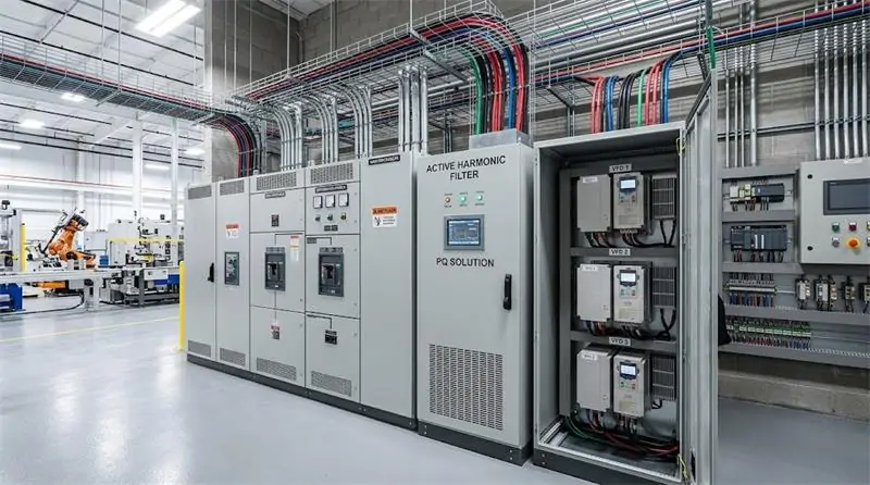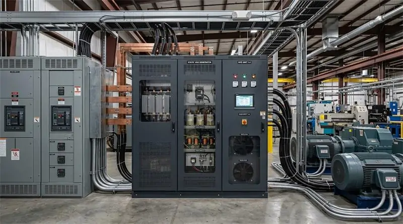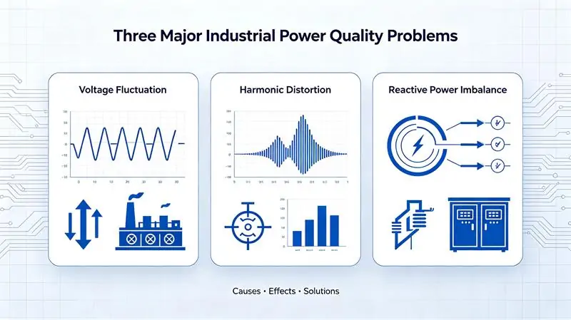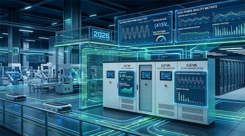
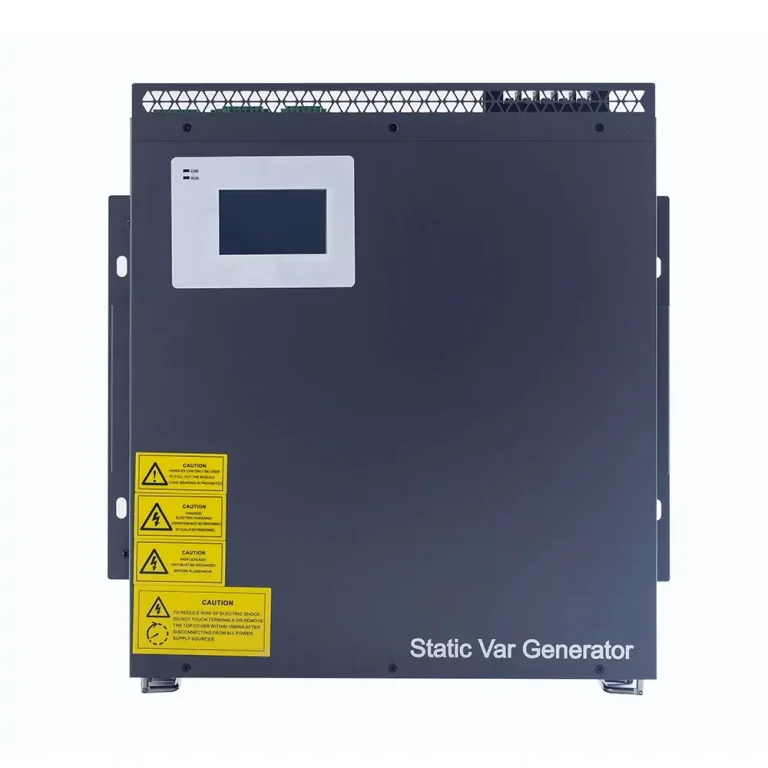




Active Power Filter (APF) technology has moved from a specialized power-quality tool to an increasingly important part of modern electrical distribution design. As facilities add variable frequency drives, UPS systems, rectifiers, EV chargers, solar inverters, battery systems, and other power-electronic loads, harmonic currents can become a practical engineering problem rather than a theoretical one.
From an engineering perspective, the most important point is simple: an APF should not be selected because a facility has “harmonics” in general. It should be selected because measured harmonic behavior, load characteristics, electrical architecture, and the required compensation target justify a specific compensation current and configuration.
GEYA uses the term Active Harmonic Filter (AHF) for its active filtering product family, while the product documentation also describes the equipment as an active power filter. For SEO and engineering communication, APF and AHF can therefore be discussed together, while AHF remains GEYA’s official product terminology.
What Is an Active Power Filter (APF)?
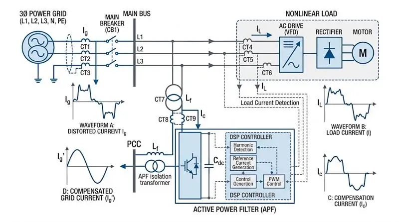
An Active Power Filter (APF) is a power-electronic compensation device connected in parallel with an electrical system. It continuously detects the load current, identifies unwanted harmonic components, and generates a compensation current with the appropriate magnitude and opposite phase to reduce the harmonic current flowing through the system.
In GEYA’s AHF architecture, the equipment detects load current in real time, separates harmonic current according to the specified harmonic detection algorithm, and generates a control signal based on the configured filtering percentage. The power stage then produces a compensation current to counter the load harmonic current.
This operating principle is fundamentally different from a passive filter. A passive filter relies on fixed components and predetermined frequency characteristics. An APF is an active system that continuously measures changing electrical conditions and dynamically adjusts its compensation current.
That distinction becomes particularly important in facilities where the nonlinear load profile changes throughout the day.
Why APF Matters in Modern Electrical Distribution
Modern facilities are increasingly dominated by power electronic equipment. Variable frequency drives, rectifiers, UPS systems, switching power supplies, battery chargers, EV charging equipment, solar inverters, and other converter-based loads can inject harmonic currents into the distribution system.
Harmonic current can contribute to additional conductor and transformer losses, overheating, waveform distortion, unwanted electrical interaction, and stress on sensitive equipment. The engineering objective is therefore not simply “make the waveform look better.” The objective is to create a more predictable electrical environment for the complete distribution system.
For U.S. industrial and commercial projects, IEEE 519-2022 is an important reference for harmonic control at the point of common coupling (PCC). It is particularly important to understand that IEEE 519 is aimed at system conditions at the PCC rather than serving as a universal product specification for an APF.
Why GEYA APF Can Be an Important Part of a Power Quality Strategy
For facilities with significant nonlinear loads, an APF can become an essential component of the power-quality system because it can respond to changing harmonic demand instead of relying only on a fixed passive network.
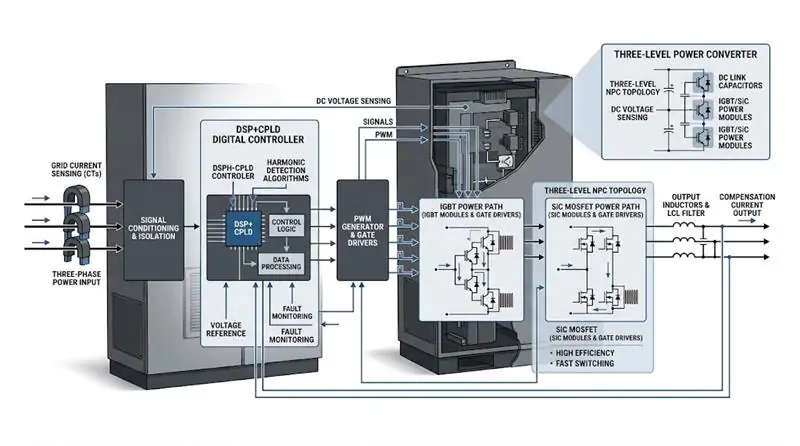
According to the GEYA power-quality catalog, the GY-AHF family uses a full-digital DSP+CPLD control core, three-level topology, advanced harmonic detection algorithms, PWM control, and modular architecture. The catalog specifies harmonic compensation across the 2nd to 50th harmonics with a current harmonic compensation capability of ≥95% for the applicable AHF configurations.
The catalog also specifies optional harmonic compensation and harmonic-plus-three-phase-unbalance compensation modes, with the residual unbalance degree after compensation specified as ≤5% for supported configurations.
Another practical advantage is modular expansion. Multiple modules can operate in parallel, allowing project capacity to be configured around the actual harmonic current requirement rather than forcing every application into one fixed equipment size.
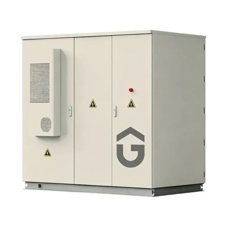
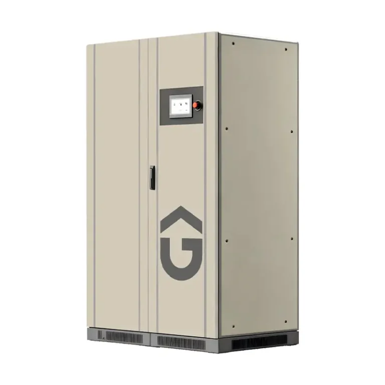
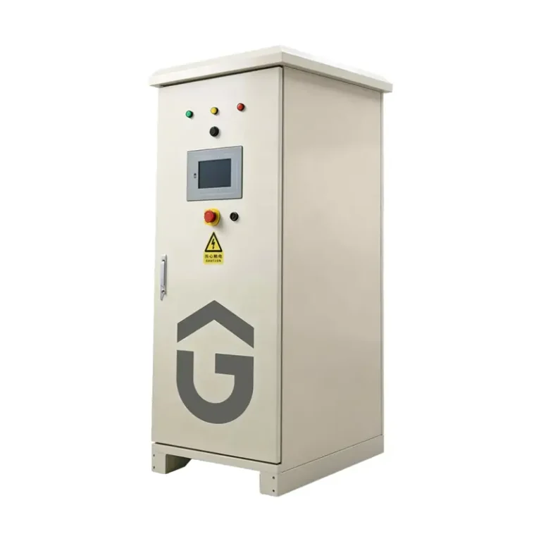
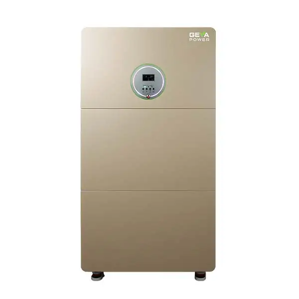
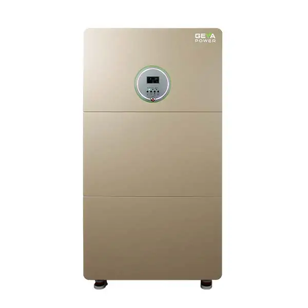
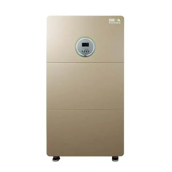
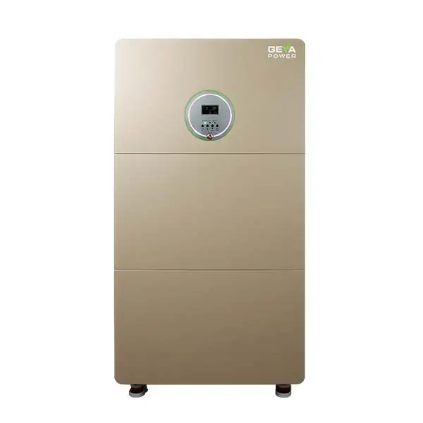
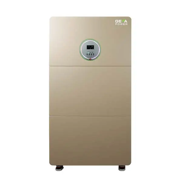
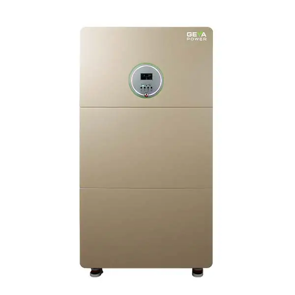
For the complete product range, see the GEYA Active Harmonic Filter (AHF) Series.
APF vs. Passive Filtering: When Does Active Compensation Make More Sense?
Passive filters can still be useful in the right application, especially where the harmonic spectrum is relatively stable and the design conditions are well understood. However, they become less attractive when load conditions change significantly, the harmonic spectrum is broad, or the facility contains multiple operating states.
An APF becomes more attractive when:
- harmonic current changes significantly with production load;
- multiple harmonic orders need to be controlled;
- the facility has mixed nonlinear loads;
- future load expansion is expected;
- modular capacity expansion is desirable;
- three-phase current imbalance needs to be addressed together with harmonics;
- the project requires active monitoring and flexible compensation settings.
The right conclusion is not that APF is always better. The correct engineering question is whether the electrical system benefits from active, continuously controlled compensation.
2026 APF Trends: Ten High-Value Solution Patterns to Watch
The following ten patterns should be understood as an engineering trend outlook rather than a ranked market-sales list. They cover three broad categories: steady-state filtering, dynamic compensation, and whole-facility optimization.
Type 1: Steady-State Harmonic Filtering
1. VFD and Motor Drive Harmonic Mitigation
Variable frequency drives remain one of the most common sources of harmonic current in industrial power systems. Manufacturing plants with large numbers of pumps, fans, compressors, conveyors, and process motors can experience a persistent harmonic load profile.
For these applications, APF design should begin with measured harmonic current rather than the horsepower rating of the motors. The key questions are which harmonic orders dominate, how much harmonic current is present at the selected connection point, and how the load changes during normal production.
GEYA’s AHF family supports harmonic compensation from the 2nd through 50th harmonics, with the compensation rate for individual harmonic orders adjustable within the specified product configuration.
2. Rectifier, UPS, and Converter-Load Harmonic Control
Large rectifier loads and UPS systems can produce significant harmonic current, particularly where large quantities of power-electronic equipment operate simultaneously.
For these facilities, the APF should be positioned according to the electrical objective. A filter installed closer to the dominant harmonic source can provide targeted compensation, while an upstream installation can be considered when the goal is to improve the aggregate condition of a distribution section.
3. Data Center Neutral-Current and Zero-Sequence Harmonic Control
Data centers deserve particular attention because the electrical architecture contains large amounts of electronic equipment, UPS systems, power supplies, and other nonlinear loads.
In three-phase four-wire systems, neutral-current behavior is especially important. The GEYA AHF documentation specifies that the neutral-line zero-sequence filtering capability can reach three times the phase-line filtering capability for the applicable models.
For a data-center project, this means the engineer should evaluate not only phase harmonic current but also neutral current and zero-sequence behavior before selecting the compensation configuration.
4. Semiconductor and High-Sensitivity Manufacturing Power Quality
Semiconductor facilities and other high-sensitivity manufacturing environments place unusually high value on electrical stability because power disturbances can affect sensitive production equipment and process consistency.
In these environments, the selection process should focus not only on harmonic compensation percentage but also on control architecture, response behavior, switching frequency, thermal design, EMC performance, and maintainability.
The GEYA GY-AHF-PLUS and GY-AHF-SiC models provide two different engineering approaches within the AHF family.
Type 2: Dynamic Compensation
5. Welding, Pressing, Cranes, and Rapidly Changing Industrial Loads
Some industrial loads do not remain stable long enough for a fixed compensation system to be the ideal answer. Welding machines, stamping presses, cranes, hoists, and other intermittently operated equipment can produce rapidly changing current conditions.
For these applications, the engineer should pay close attention to full response time, compensation capacity, current limiting, thermal conditions, and module parallel operation.
GEYA’s AHF documentation specifies a full response time of less than 40 ms for the relevant AHF configurations and a rated overload capability of 1.2 times the rated capacity for 60 seconds.
6. EV DC Fast-Charging Sites
EV charging infrastructure introduces concentrated power-electronic loads into distribution systems, especially at high-power DC fast-charging locations.
The challenge is not simply the total charger capacity. Engineers should examine how many chargers operate simultaneously, how the load changes when vehicles connect or disconnect, where the PCC is located, and how the charging system interacts with other facility loads.
For these projects, modular APF capacity can be useful because additional charging capacity may be added later. Before final selection, however, the engineer should confirm voltage compatibility, harmonic measurements, compensation current requirements, and utility requirements.
7. Renewable-Energy and Inverter-Heavy Facilities
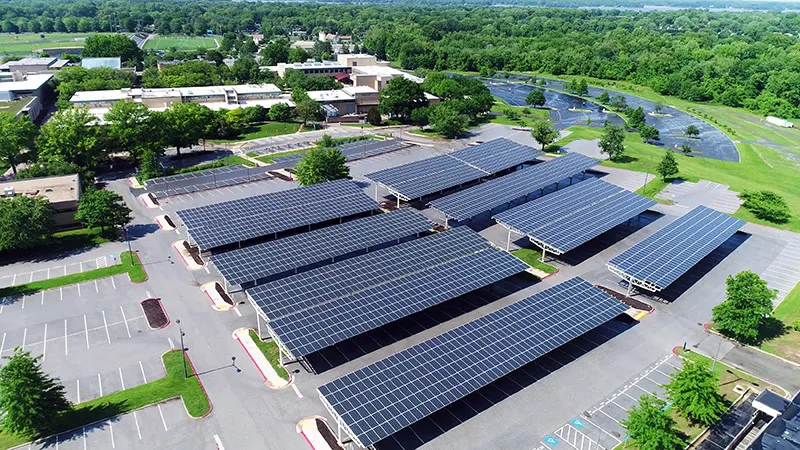
Solar PV systems, battery energy storage systems, and other inverter-based resources are changing the electrical behavior of many facilities.
Where renewable generation operates alongside nonlinear industrial loads, harmonic assessment should consider multiple operating states, including minimum load, normal production, peak production, charging, discharging, and grid-interactive operation.
This is an area where a power-quality study is more valuable than simply selecting a larger filter.
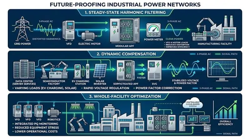
Type 3: Whole-Facility Power Quality Optimization
8. Multi-Point Modular APF Architecture
Large facilities increasingly benefit from treating harmonic compensation as a distribution-system design problem rather than installing one large device without analyzing the network.
A multi-point architecture can place compensation closer to major harmonic sources while using modular parallel units where additional capacity is required.
GEYA’s AHF product family uses modular architecture and supports multiple units operating in parallel. This makes it possible to build a compensation system around measured harmonic current instead of selecting equipment solely by the total transformer capacity.
9. APF + SVG Hybrid Power Quality Systems
One of the most important engineering distinctions is that harmonic compensation and reactive-power compensation are not the same function.
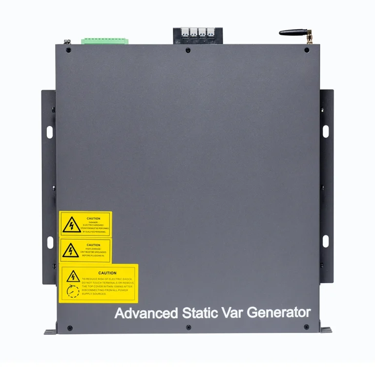
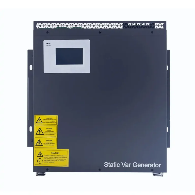
APF/AHF is primarily used for harmonic current compensation, while SVG is primarily used for dynamic reactive-power compensation and power-factor correction.
When a facility has both substantial harmonic current and a significant reactive-power problem, combining the two technologies can be technically appropriate.
See the GEYA Power Quality Management Solutions range for the relationship between AHF, SVG, ASVG, and other power-quality technologies.
10. APF + Power Quality Monitoring + Continuous Optimization
The final trend is moving from “install a filter and forget about it” to continuous power-quality management.
An APF should be viewed as part of a measurement-and-correction loop: measure the electrical problem, configure the compensation strategy, monitor the outcome, and adjust the system when the load changes.
This approach is particularly important in facilities that are expanding, adding EV chargers, increasing data-center load, installing solar generation, or modifying production equipment.
How to Select the Right GEYA APF
The biggest APF selection mistake is choosing capacity from the facility’s transformer size alone.
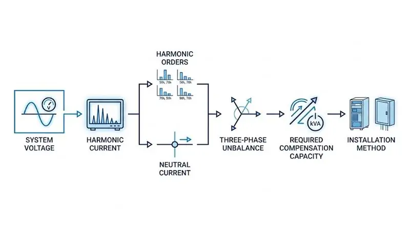
A better approach is to work through the following sequence.
Step 1: Confirm the System Voltage
Start with the actual operating voltage at the connection point.
The GEYA catalog lists AHF configurations covering AC220V, 380V, 500V, 690V, and 800V for the applicable models. The listed operating voltage tolerance is ±20% for AC220V, 380V, and 500V configurations, -20% to +15% for AC690V, and -20% to a maximum of 850V for the AC800V configuration.
For U.S. projects, this point deserves special attention because many industrial distribution systems are based on nominal 480 V architectures. Do not automatically assume that a “500 V” GEYA configuration is interchangeable with every 480 V application. Confirm actual operating voltage, tolerance, transformer arrangement, and project-specific compatibility before ordering.
Step 2: Measure the Harmonic Current
The APF rating should be based on the actual harmonic current that needs to be compensated.
At minimum, collect:
- fundamental current;
- THDi;
- individual harmonic orders;
- neutral current where applicable;
- load profile over time;
- minimum, normal, and peak operating conditions.
Do not size the APF simply because the transformer is rated at 1,000 kVA or 2,000 kVA.
Step 3: Determine Which Harmonic Orders Matter
GEYA’s AHF documentation specifies compensation from the 2nd to 50th harmonics, with adjustable compensation rates for individual harmonic orders.
In practical engineering, however, it is still important to determine which orders actually dominate the system. A facility with primarily lower-order harmonics should not be analyzed in exactly the same way as a system with a broader harmonic spectrum and significant high-frequency components.
Step 4: Decide Whether Unbalance Compensation Is Needed
If the electrical system has three-phase load imbalance in addition to harmonic current, select a configuration that supports the combined compensation mode where required.
The relevant GEYA AHF configurations specify a post-compensation unbalance degree of ≤5%.
Step 5: Evaluate Neutral Current
For three-phase four-wire systems, especially those with substantial electronic loads, neutral-current behavior should be part of the selection study.
For the applicable GEYA AHF models, neutral-line filtering capability is specified at three times the phase-line filtering capability.
Step 6: Select the Installation Architecture
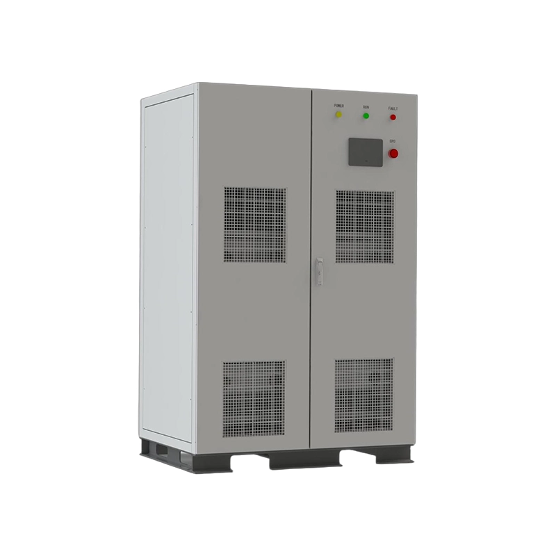
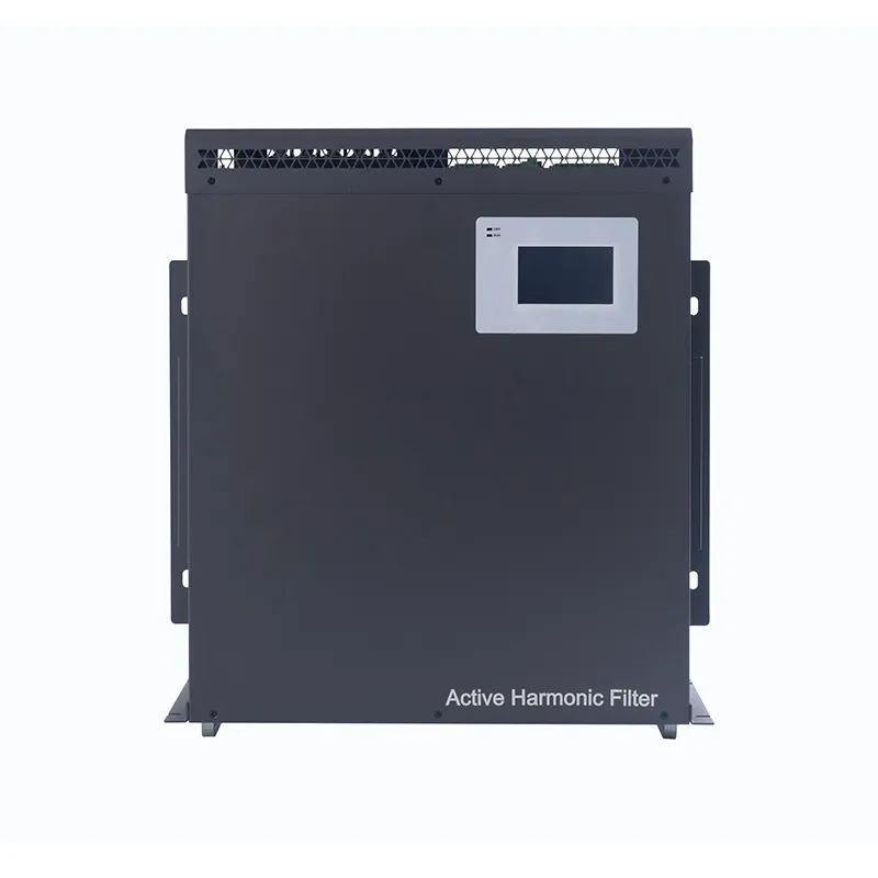
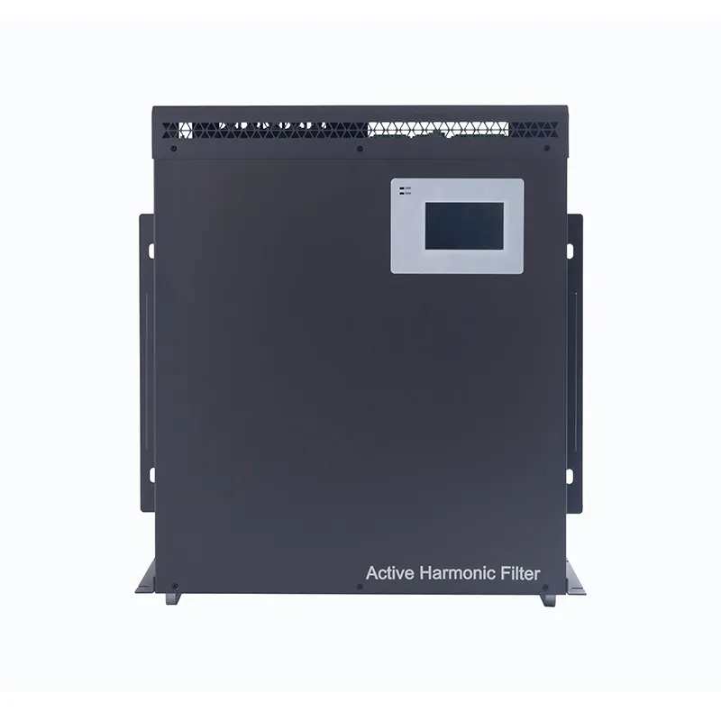
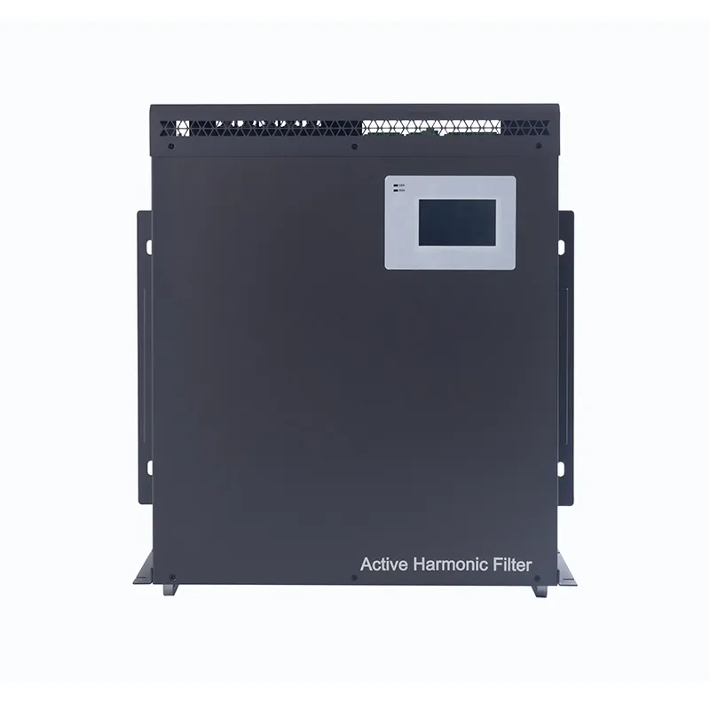
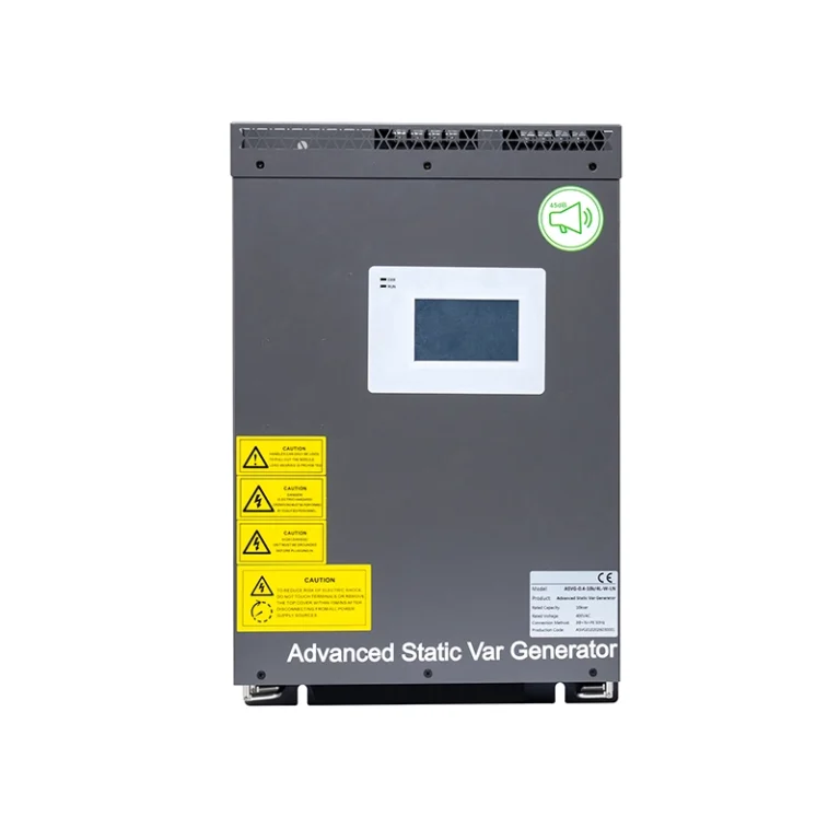
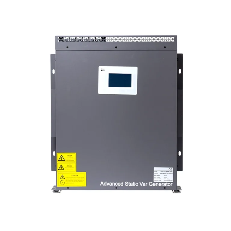
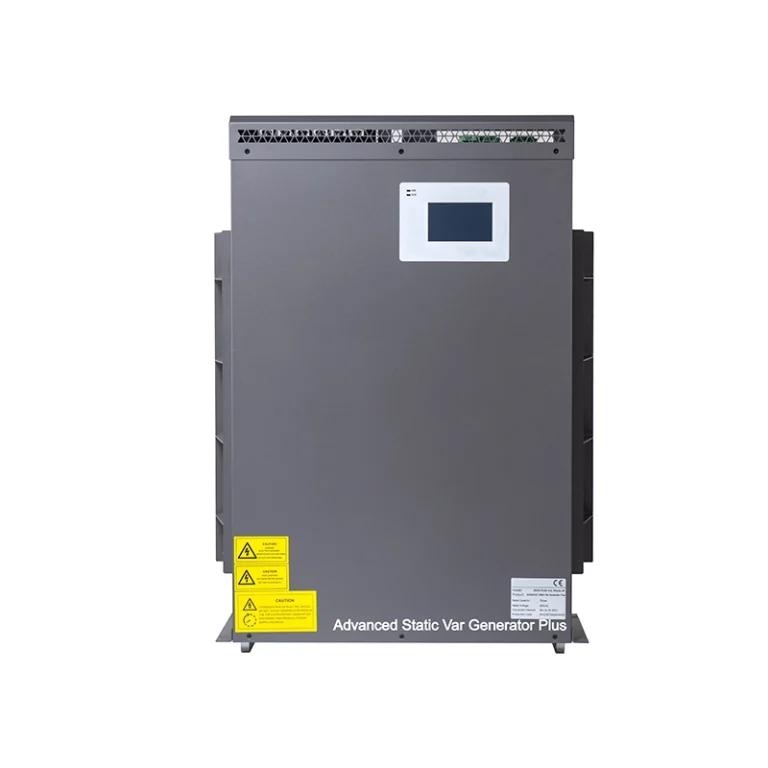
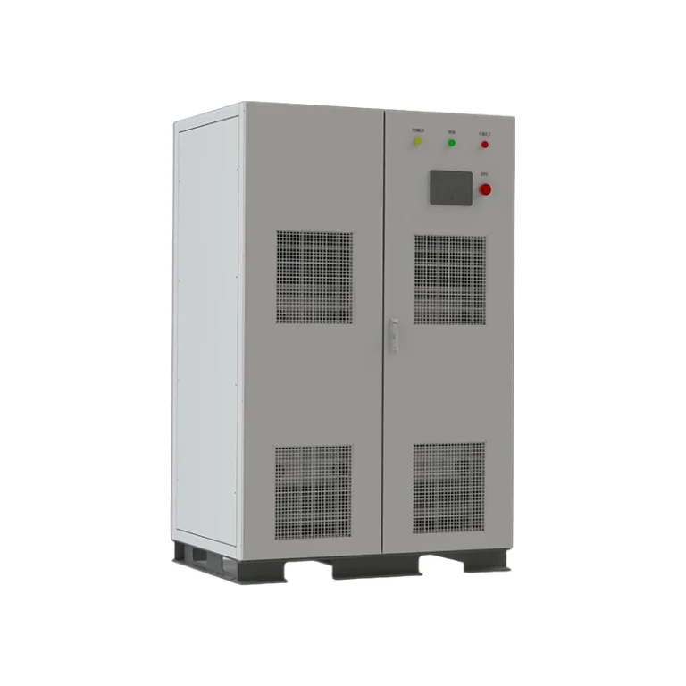
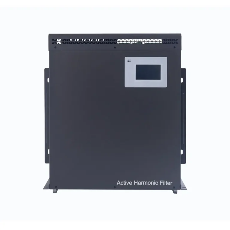
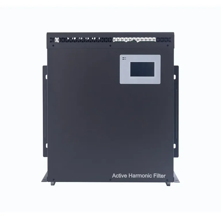
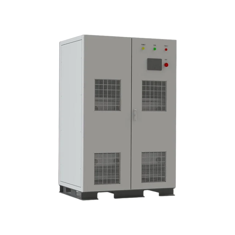
The GEYA catalog provides rack-mounted and wall-mounted module configurations, while the GY-AHF Cabinet provides an integrated cabinet solution.
A compact modular solution may make sense when space and future expansion matter. A cabinet solution can be more appropriate when a large centralized compensation capacity is needed.
GEYA AHF Product Family: What the Catalog Actually Specifies
The following summary is based directly on the GEYA 202607 Power Quality Catalog.
| Model | Key Voltage / Capacity Data | Harmonic Compensation | Efficiency / Switching | Key Architecture |
|---|---|---|---|---|
| GY-AHF | 220V: 25A 380V: 7/15/25/50/75/100/150/200A 500V: 100A 690V: 100A 800V: 100A |
2nd–50th ≥95% |
≥97% overall efficiency 16kHz / 12.8kHz depending on configuration |
DSP+CPLD Three-level topology Modular parallel operation |
| GY-AHF-PLUS | 220V / 380V 100A / 150A |
2nd–50th ≥95% |
≥97% overall efficiency 16kHz |
DSP+CPLD Three-level topology 3× neutral-line filtering Class A EMC |
| GY-AHF-SiC | 220V / 380V 100A / 150A modules |
2nd–50th ≥95% |
≥97% overall efficiency 30kHz switching Peak efficiency >98.5% |
SiC power devices High power density modular design Up to 8 modules / 1200A cabinet capacity |
| GY-AHF-cabinet | 220V / 380V / 500V / 690V / 800V Capacity varies by voltage/configuration |
2nd–50th ≥95% |
≥97% overall efficiency 16kHz / 12.8kHz depending on configuration |
Integrated cabinet Modular design Forced-air cooling |
For the exact project configuration, always use the official technical datasheet and confirm the final model, capacity, voltage, installation conditions, and protection configuration with GEYA before purchase.
Inside the GEYA APF: Power Modules and Control Hardware
When evaluating an APF, many buyers focus almost entirely on the headline compensation percentage. Engineers should look deeper.
Power Stage: IGBT and SiC Power Devices
For the standard AHF architecture, the GEYA catalog describes an IGBT-based power stage working with a three-level topology and digital PWM control.
For the GY-AHF-SiC, GEYA specifically identifies SiC power devices as the core power technology. The catalog specifies a 30 kHz switching frequency, peak efficiency above 98.5%, high power density, and a maximum cabinet capacity of 1200A with up to eight modules.
From an engineering standpoint, the SiC architecture is particularly interesting where efficiency, thermal performance, power density, switching frequency, and installation footprint are high priorities.
However, higher semiconductor performance does not automatically mean that a SiC APF is the correct solution for every facility. The project should still be evaluated according to harmonic load, required capacity, environment, service conditions, and total lifecycle economics.
Main Control: DSP + CPLD Digital Architecture
Across the GEYA AHF family, the catalog specifies a DSP+CPLD full-digital control core.
This architecture is well suited to real-time harmonic detection, control calculation, PWM coordination, protection logic, and fast compensation control. The important engineering point is not simply the chip naming. What matters is how effectively the complete control architecture converts measured harmonic current into a stable and accurate compensation current.
One important limitation should also be stated clearly: the GEYA catalog identifies the DSP+CPLD architecture, but it does not identify the exact semiconductor manufacturer or detailed chip part numbers. Therefore, a buyer should not assume a specific chip brand or model unless GEYA provides that information separately for the project.
APF Deployment: The Installation Point Matters as Much as the Device
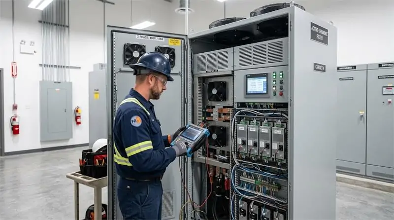
An APF can be technically correct and still deliver disappointing project results if it is installed at the wrong electrical location or paired with an incorrect current-sensing arrangement.
Before installation, engineers should define:
- the target compensation point;
- the harmonic source;
- the CT sampling location;
- the direction and polarity of CTs;
- the electrical relationship between the APF, load, transformer, and PCC;
- the expected operating states of the facility.
For a single major harmonic source, localized compensation may be appropriate. For multiple distributed harmonic sources, a centralized cabinet or multiple modular compensation points may be more practical.
For critical facilities, commissioning should compare the system before and after compensation using actual measured data rather than relying only on the APF display.
Environmental Conditions That Should Not Be Ignored
The GEYA catalog specifies operating conditions that should be considered during design.
- Altitude: below 2000 m; above 2000 m, derating is required according to GB/T 3859.2.
- Ambient temperature: -10°C to +50°C; above 40°C, capacity derating does not exceed 30% as specified in the catalog.
- Relative humidity: ≤90%, with no condensation under the specified conditions.
- Pollution degree: Class III or below.
- Protection rating: IP20 as standard, with IP54 available/customizable for applicable configurations.
- Cooling: forced-air cooling for the applicable modular AHF configurations.
These numbers matter because an APF installed in a clean electrical room and an APF installed in a hot, dusty industrial environment do not experience the same thermal and maintenance conditions.
My Practical APF Maintenance Routine
Good APF maintenance is not complicated. It is mostly about consistency.
1. Review the Alarm and Event History
Do this regularly rather than waiting for a visible failure. Repeated overtemperature, overcurrent, undervoltage, frequency abnormalities, or communication alarms can reveal problems before they become major downtime events.
2. Check Cooling Airflow
Because the applicable GEYA AHF configurations use forced-air cooling, blocked airflow, dust accumulation, or abnormal fan operation can directly affect thermal performance.
Keep the air inlet and outlet unobstructed and inspect the ventilation path according to the site’s maintenance schedule.
3. Trend Harmonic Measurements
Do not only look at today’s THDi value. Compare the present condition with commissioning data.
If a plant slowly adds drives, chargers, UPS equipment, or inverter-based equipment, the harmonic profile can change even while the original APF continues to operate normally.
4. Verify CT Wiring After Electrical Modifications
Whenever the distribution system is modified, CT polarity, phase sequence, sensing position, and control wiring should be rechecked by qualified electrical personnel.
An incorrectly installed current sensor can create control problems that may look like a software issue.
5. Check Module Current Sharing in Parallel Systems
For systems using multiple parallel modules, engineers should pay attention to whether the modules are sharing compensation demand as expected.
A persistent abnormal imbalance between modules can be a useful maintenance signal even before a protection alarm appears.
6. Maintain a Baseline
The best maintenance record is the commissioning baseline: supply voltage, harmonic current, dominant harmonic orders, neutral current where applicable, operating load, and APF output.
Future measurements should be compared with that baseline.
7. Never Perform Internal Maintenance on Energized Equipment
APF equipment contains high-energy electrical components. Inspection, service, or internal maintenance should be performed only by qualified personnel using the site’s approved isolation and lockout/tagout procedures.
APF vs. SVG vs. ASVG: Choose the Technology for the Problem
| Technology | Primary Problem | Typical Purpose |
|---|---|---|
| APF / AHF | Harmonic current | Reduce harmonic distortion and improve waveform quality |
| SVG | Reactive power / power factor | Dynamic reactive power compensation and power factor correction |
| ASVG | Multiple power quality problems | Integrated reactive power, harmonic, and three-phase unbalance compensation |
This distinction prevents one of the most common purchasing mistakes: asking one device to solve a problem that belongs to another compensation technology.
When a system has both harmonic and reactive-power problems, a coordinated AHF + SVG architecture may be appropriate. When several compensation objectives need to be addressed through one integrated technology, an ASVG may deserve evaluation.
A Practical APF Selection Checklist for B2B Buyers
Before requesting an APF quotation, prepare the following information:
- System voltage and frequency
- Three-phase three-wire or three-phase four-wire configuration
- Measured load current
- Measured harmonic current
- THDi and individual harmonic orders
- Neutral current where applicable
- Required compensation percentage
- Whether three-phase unbalance compensation is needed
- Installation location and available space
- Ambient temperature and environmental conditions
- Future load expansion plans
- Communication requirements
The more complete this information is, the more accurately the APF capacity can be matched to the actual electrical system.
Final Engineering Takeaway
The future of APF deployment is not simply about buying equipment with a higher headline specification.
The better approach is to treat harmonic mitigation as an electrical-system engineering problem.
Measure the harmonic current. Understand the load. Identify the dominant harmonic orders. Check the neutral system. Select the compensation capacity. Choose the right installation architecture. Then verify the result with actual measurements.
GEYA’s AHF portfolio provides several technical paths within this framework: the standard GY-AHF, the high-spec GY-AHF-PLUS, the SiC-based GY-AHF-SiC, and the integrated GY-AHF-cabinet. The catalog provides configurations across different voltage and compensation-current requirements, while modular parallel operation allows the compensation system to be built around the actual project requirement.
For facilities facing harmonic distortion, unstable current waveforms, nonlinear-load expansion, or increasingly complex electrical loads, APF technology deserves to be considered as part of a broader power-quality strategy rather than as an isolated piece of equipment.
Explore GEYA Active Harmonic Filter (AHF) Solutions →
Frequently Asked Questions About Active Power Filters
What does APF stand for?
APF stands for Active Power Filter. In harmonic mitigation applications, the technology is also commonly described as an Active Harmonic Filter (AHF).
What problems does an APF solve?
An APF is primarily used to detect and compensate harmonic current. Depending on the specific model and configuration, it can also support three-phase unbalance compensation.
What harmonic orders can GEYA AHF compensate?
The GEYA catalog specifies compensation from the 2nd to 50th harmonics, with an overall current harmonic compensation capability of ≥95% for the applicable configurations.
How fast can GEYA AHF respond?
The GEYA catalog specifies a full response time of less than 40 ms for the applicable AHF configurations.
Can APF improve power factor?
APF’s primary role is harmonic compensation, not dynamic reactive-power compensation. If power-factor correction is also required, an SVG or another suitable reactive-power compensation technology should be evaluated.
What is the difference between GY-AHF-PLUS and GY-AHF-SiC?
GY-AHF-PLUS uses the GEYA high-spec AHF architecture with DSP+CPLD digital control, three-level topology, 16 kHz switching, and modular 100A/150A configurations for AC220V/380V systems. GY-AHF-SiC uses SiC power devices, a higher 30 kHz switching frequency, peak efficiency above 98.5%, and a high-density modular architecture that can support up to eight modules and 1200A per cabinet according to the catalog.
Can multiple GEYA AHF modules operate in parallel?
Yes. The GEYA catalog specifies modular designs that support multiple modules connected in parallel, allowing compensation capacity to be expanded according to project requirements.