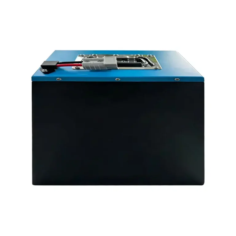
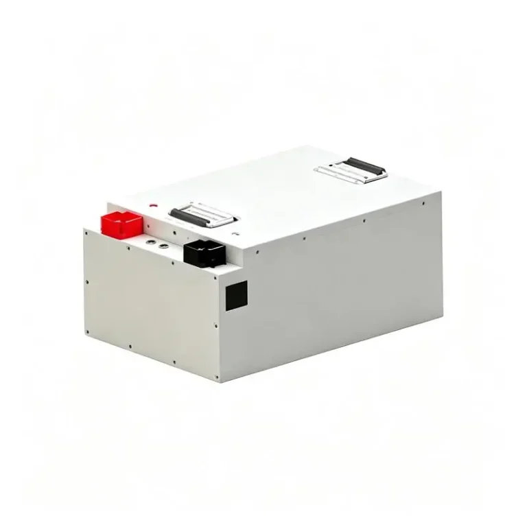
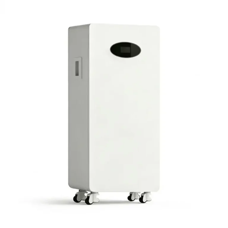
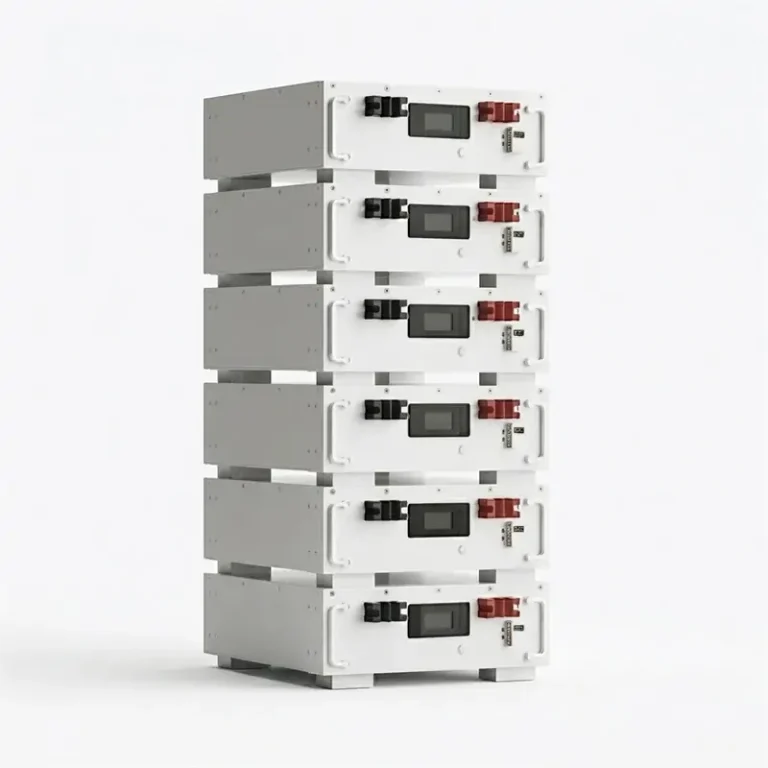
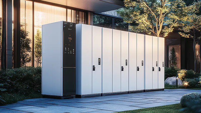
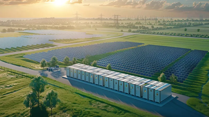
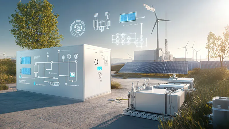
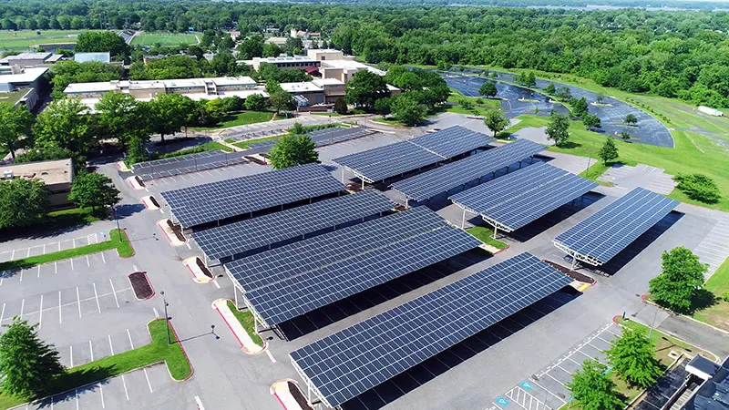
Commercial and industrial energy storage is moving beyond simple battery backup. For factories, warehouses, cold-storage facilities, commercial buildings, EV charging sites, and remote industrial operations, a well-designed Commercial & Industrial Energy Storage System (C&I ESS) can reduce peak electricity costs, increase solar self-consumption, improve power resilience, and coordinate multiple energy sources.
For U.S. commercial and industrial customers, the business case often starts with the utility bill. Time-of-use (TOU) rates, demand charges, solar export limitations, and the cost of production downtime can all influence the required battery capacity and power rating.
However, selecting a C&I ESS is not simply a matter of choosing a battery with enough kWh. Engineers and EPC contractors must evaluate the facility’s load profile, peak demand, critical loads, PV generation, inverter capacity, backup duration, operating mode, and future expansion requirements.
This guide explains the core architecture, sizing methodology, product selection logic, and typical applications of C&I energy storage systems, with practical examples based on GEYA’s commercial and industrial energy storage solutions.
1. Why C&I Facilities Need Dedicated Energy Storage Today
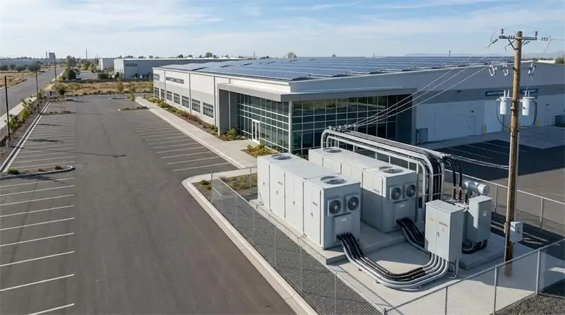
Energy management has become a strategic operating issue for commercial and industrial facilities. A factory may consume hundreds or thousands of kilowatt-hours every day, while its highest-demand periods can significantly increase electricity costs.
At the same time, manufacturing equipment, automation systems, refrigeration equipment, data networks, and other critical loads can be highly sensitive to power interruptions.
For these facilities, energy storage provides a controllable energy buffer between generation, the utility grid, and the facility’s electrical loads.
1.1 The Three-Way Challenge of Modern Industrial Power
Modern C&I facilities commonly face three interconnected energy challenges: rising peak electricity costs, grid reliability concerns, and increasing pressure to reduce carbon emissions.
Peak Electricity Costs and Time-of-Use Rates
Many U.S. utilities use time-of-use pricing or demand-based billing structures. Electricity consumed during high-demand periods can cost more than electricity consumed during lower-demand periods.
A properly sized battery energy storage system can charge when electricity is less expensive and discharge during selected peak periods. This strategy is commonly referred to as peak shaving.
Grid Instability and Power Outages
A short utility interruption can create a disproportionate financial impact when it stops an automated production line, refrigeration system, server environment, or process-control system.
Energy storage can provide backup power to designated critical loads and, depending on the system architecture, support fast transition between grid-connected and backup operating modes.
Solar Integration and Carbon Reduction
Commercial facilities with rooftop or ground-mounted PV systems may generate more solar electricity than they can immediately consume.
Instead of exporting excess generation when export capacity is limited or electricity prices are unfavorable, an ESS can store available solar energy and release it later when facility demand increases.
1.2 Key Value Propositions for Commercial Users
Peak Shaving and Demand Charge Reduction
During a peak demand event, the battery can discharge to reduce the amount of power drawn from the utility.
The objective is not necessarily to supply the entire facility from the battery. In many projects, the more practical strategy is to use battery power to reduce the facility’s highest grid import and flatten the load curve.
Example: If a facility normally reaches a 300 kW demand peak, a properly controlled ESS could discharge during selected peak periods to reduce the grid contribution. The actual savings depend on the utility tariff, demand-charge structure, operating schedule, and battery dispatch strategy.
Backup Power for Critical Loads
Not every facility needs to back up its entire electrical system.
A more economical approach is often to identify critical loads such as servers, control systems, refrigeration, security systems, communication equipment, or selected production machinery and connect them to a protected backup power path.
This allows the ESS to provide meaningful resilience without requiring a battery large enough to power the entire facility.
Maximizing Solar PV Self-Consumption
When solar generation exceeds immediate facility demand, the ESS can store the excess energy for later use.
This solar-plus-storage strategy can increase the percentage of PV electricity consumed on-site and reduce dependence on utility electricity during later operating periods.
1.3 C&I ESS vs. Residential Energy Storage
Commercial and industrial systems are not simply oversized residential batteries.
A C&I project may require higher three-phase power output, more sophisticated energy dispatch, larger PV input capacity, integration with generators, grid-forming operation, parallel operation, industrial protection, and more demanding thermal-management requirements.
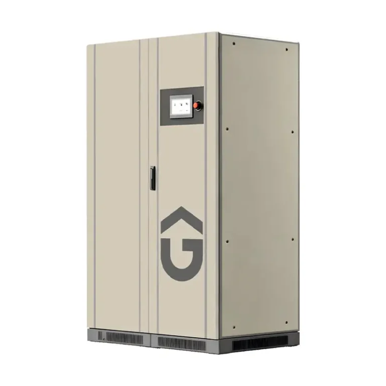
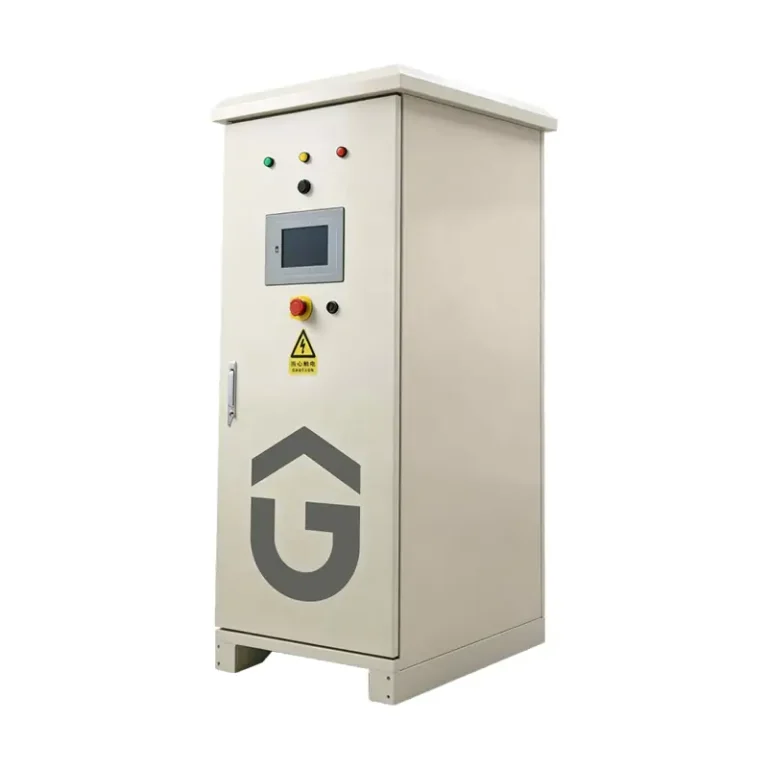
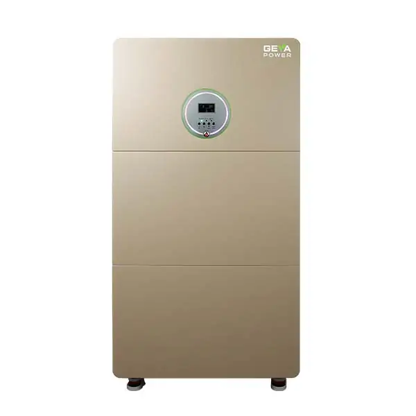
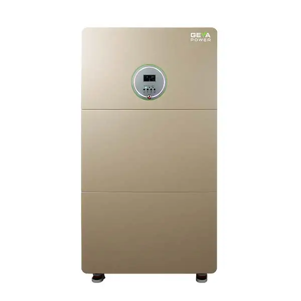
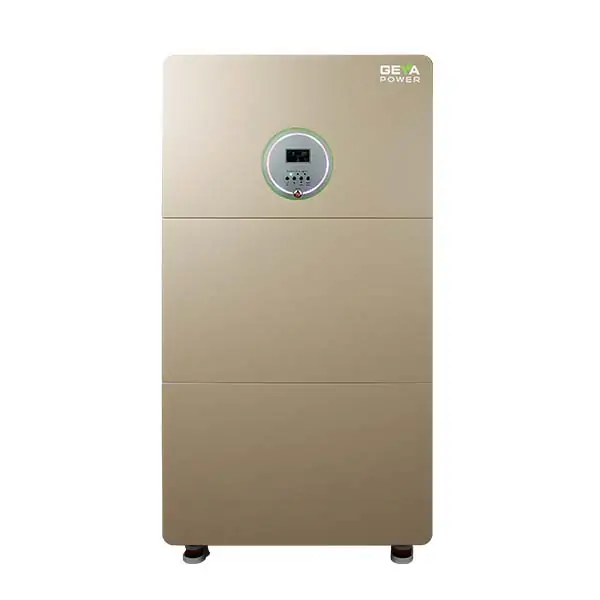
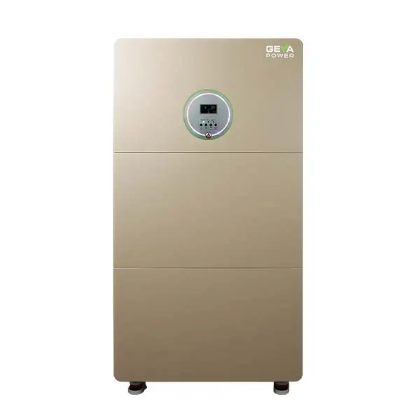
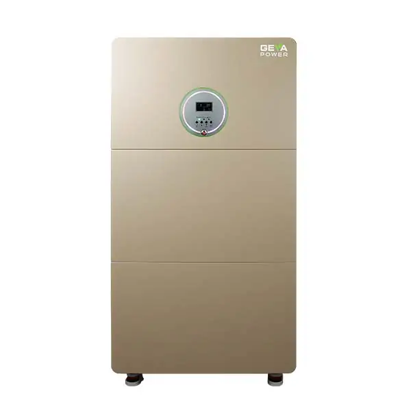
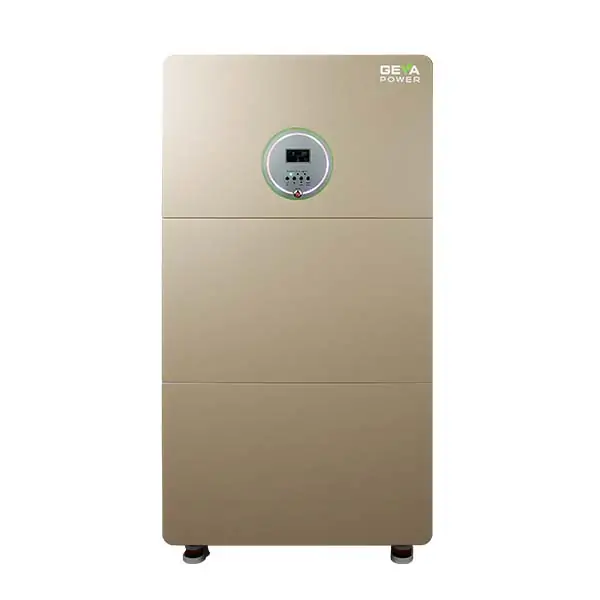
For example, GEYA’s C&I product range includes compact three-phase all-in-one systems such as the GYS 3312K and GYS 3315K, as well as larger integrated microgrid systems such as the GYS 100HS-215KWH and GYS 250H.
The key difference is therefore not simply battery size. It is the ability to coordinate power conversion, energy storage, PV generation, utility power, backup loads, and other energy sources as one engineered system.
2. Core Architecture of a C&I All-in-One Solar-Storage System
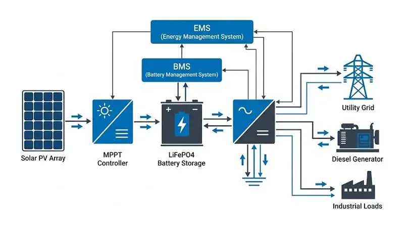
An all-in-one C&I ESS combines multiple energy-management functions into a coordinated system. This reduces the number of separate components that EPC contractors need to integrate and can simplify commissioning and system control.
2.1 The All-in-One Integration Philosophy
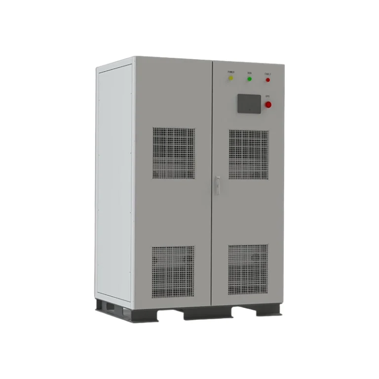
Depending on the model, GEYA’s integrated C&I systems combine functions such as PCS, PV MPPT, EMS, grid/off-grid transfer control, and AC/DC power distribution within a standardized cabinet.
For example, the GYS 100/150HS integrates PCS, PV MPPT, EMS, STS transfer control, and AC/DC distribution, while supporting connections to PV, batteries, utility power, and diesel generators.
This architecture allows the system to coordinate multiple energy sources rather than treating the battery as a standalone backup device.
2.2 Critical Hardware Subsystems
LiFePO4 Battery System
LiFePO4 chemistry is widely used in stationary energy storage because of its combination of safety characteristics, cycle performance, and suitability for high-use applications.
However, battery voltage and configuration vary significantly between C&I products. For example, the GYS 100HS-215KWH uses a 768 V battery architecture with 215.04 kWh rated energy, while the GYS 3312K and GYS 3315K use a 51.2 V battery architecture with modular battery configurations.
This is an important engineering distinction when comparing different ESS platforms.
Bidirectional Power Conversion
The PCS or integrated inverter controls bidirectional energy flow between the battery and the AC electrical system.
In a grid-connected application, the system can charge or discharge the battery according to the configured energy strategy. In backup or microgrid operation, the power conversion system can support the designated loads while coordinating available generation sources.
EMS and Smart Energy Monitoring
The Energy Management System (EMS) is responsible for coordinating energy flows among PV, battery storage, grid power, loads, and other available sources.
Typical control strategies include:
- Peak shaving
- Time-of-use energy shifting
- PV self-consumption
- Zero-export or anti-reverse-power control
- Battery charging and discharging management
- Diesel generator coordination
- Grid-connected and off-grid operating strategies
GEYA’s larger C&I systems support EMS functions for multi-source energy scheduling, including PV, batteries, grid power, diesel generators, and loads.
3. Step-by-Step Guide: How to Size a C&I Energy Storage System
Correct ESS sizing starts with the electrical load rather than the battery catalog.
An EPC contractor or system engineer should first determine what the facility needs the ESS to accomplish. Peak shaving, solar self-consumption, backup power, and off-grid operation can produce very different sizing results.
3.1 Step 1: Audit the Load Profile and Operating Scenarios
Collect at least the following information:
- Average facility load in kW
- Maximum facility demand in kW
- Short-duration peak or motor-starting demand
- Daily energy consumption in kWh
- Critical load in kW
- Required backup duration in hours
- Daily PV generation profile
- Utility tariff and demand-charge structure
For a U.S. facility, interval utility data at 15-minute resolution can be particularly useful for understanding demand peaks and determining when battery dispatch would create the greatest economic benefit.
3.2 Step 2: Size the Inverter or PCS Power Rating
The inverter or PCS must be capable of handling the required continuous load and relevant short-duration power events.
A basic preliminary sizing equation is:
PPCS ≥ Ppeak load × Safety Factor
For an early-stage feasibility estimate, a safety factor such as 1.25 may be used as a starting point. The final value should be determined from actual load data, motor-starting characteristics, inverter overload capability, and the selected operating mode.
Do not automatically apply a 1.25 factor to every project. Large motors, compressors, pumps, and other inductive loads may require a more detailed transient analysis.
3.3 Step 3: Calculate Battery Storage Capacity
Battery energy capacity depends on the critical load, required backup duration, allowable depth of discharge, and overall system efficiency.
A practical preliminary calculation is:
Ebatt (kWh) = Critical Load (kW) × Backup Hours ÷ (DoD × System Efficiency)
Example:
If the critical load is 100 kW and the required backup time is 2 hours, with a 90% usable depth of discharge and approximately 90% overall system efficiency:
Ebatt = 100 × 2 ÷ (0.90 × 0.90) ≈ 247 kWh
This indicates that a system in the approximately 250 kWh class would be a reasonable starting point for further engineering review.
Actual battery selection must also consider battery operating voltage, maximum charge/discharge power, ambient temperature, aging, reserve SOC, battery management strategy, and the manufacturer’s recommended operating limits.
3.4 Step 4: Size the PV Array and MPPT Configuration
PV sizing should be considered together with battery capacity and the facility’s daily load profile.
For example, the GYS 3312K supports up to 24 kW PV input, up to 1000 V maximum PV voltage, and an MPPT operating range of 200–800 V. The GYS 3315K supports up to 30 kW PV input with a maximum PV voltage of 1000 V and the same 200–800 V MPPT range.
For larger systems, the GYS 100HS-215KWH supports up to 1000 V PV input with an MPPT range of 250–1000 V and configurable PV power levels.
PV string design must always be checked against the inverter’s voltage limits, temperature-corrected open-circuit voltage, MPPT operating range, current limits, and local electrical-code requirements.
3.5 Practical C&I ESS Sizing Matrix
| Application | Typical Load Range | Potential ESS Class | Primary Objective |
|---|---|---|---|
| Small Workshop / Commercial Facility | 15–30 kW | 15–45 kWh | Solar self-consumption, peak shaving, backup |
| Medium Manufacturing Facility | 50–150 kW | 100–215+ kWh | Peak shaving, backup, solar integration |
| Mining / Remote Microgrid | 100–250 kW+ | 215 kWh–1 MWh+ | Microgrid operation, diesel reduction, backup |
These ranges are preliminary engineering references rather than fixed product-selection rules. The final system should be sized from actual interval load data, PV production data, utility tariffs, required backup loads, and the selected equipment’s electrical limits.
4. GEYA C&I ESS Hardware Solutions: Matching Models to Projects
GEYA’s C&I ESS portfolio covers compact three-phase integrated systems as well as larger microgrid-oriented cabinets. The correct model depends on the required power, battery capacity, PV input, operating mode, and project environment.
4.1 Small-to-Medium C&I: Three-Phase Integrated Systems
GYS 3312K — 12 kW / 15.36 or 30.72 kWh
The GYS 3312K is a three-phase all-in-one PV-storage inverter/controller designed for residential, commercial, and small industrial applications.
- 12 kW rated off-grid output
- 15.36 kWh or 30.72 kWh battery configuration
- LiFePO4 battery
- 380/400 V three-phase output
- Up to 24 kW PV input
- Maximum PV input voltage: 1000 V
- MPPT range: 200–800 V
- Maximum PV efficiency: up to 98%
- Supports CT-based anti-backflow control
- Supports Wi-Fi, APP, RS485 and BMS communication
It can be considered for smaller commercial buildings, workshops, small industrial loads, and solar-plus-storage backup applications.
View GYS 3312K technical specifications →
GYS 3315K — 15 kW / 15.36–46.08 kWh
The GYS 3315K provides a higher 15 kW three-phase output and supports three battery configurations.
- 15 kW rated off-grid output
- 15.36 kWh / 30.72 kWh / 46.08 kWh battery configurations
- LiFePO4 battery
- 380/400 V three-phase output
- Up to 30 kW PV input
- Maximum PV input voltage: 1000 V
- MPPT range: 200–800 V
- Maximum PV efficiency: up to 98%
- Battery efficiency: up to 94.5%
- CT-based anti-backflow protection
- Wi-Fi + APP monitoring
This platform is particularly useful where a compact three-phase solar-plus-storage architecture is preferred.
View GYS 3315K technical specifications →
4.2 Large-Scale C&I and Microgrid Cabinets
GYS 100HS-215KWH — 100 kW / 215.04 kWh
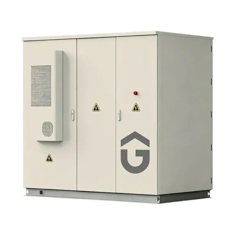
The GYS 100HS-215KWH is a larger integrated microgrid energy storage system combining power conversion, PV input, battery storage, EMS control, and multi-source energy coordination.
- 100 kW rated output power
- 215.04 kWh rated battery energy
- 400 V AC system
- 768 V battery architecture
- Up to 1000 V PV input
- 250–1000 V MPPT operating range
- 0.5P maximum charge/discharge rate at 25°C
- IP54 protection
- Temperature-controlled intelligent air cooling
- Supports PV, grid, battery, diesel generator and loads
- RS485 and TCP/IP EMS communication
The system is suited to industrial facilities, solar-storage microgrids, backup applications, remote sites, construction projects, and oilfield or other demanding outdoor applications.
View GYS 100HS-215KWH technical specifications →
GYS 250H — 250 kW Microgrid All-in-One System
For higher-power microgrid projects, the GYS 250H provides 250 kW rated power with integrated PCS, PV MPPT, EMS, ATS, and AC/DC distribution functions.
- 250 kW rated grid-connected output
- 275 kW maximum off-grid output
- 400/230 V three-phase output
- 680–900 V battery operating range
- Up to 950 V maximum battery voltage
- PV capacity: 120 kW × 2
- PV input range: 600–900 V
- Up to 3 units in parallel
- IP54 protection
- Intelligent forced-air cooling
- Active transfer: 0 ms; passive transfer: <10 ms
The GYS 250H is designed for industrial microgrids, renewable-energy projects, backup systems, remote sites, and solar-storage-diesel configurations where higher power and multi-source coordination are required.
View GYS 250H technical specifications →
4.3 C&I ESS Product Comparison
| Model | Rated Output | Battery Capacity | AC Voltage | PV Input | Typical Application |
|---|---|---|---|---|---|
| GYS 3312K | 12 kW | 15.36 / 30.72 kWh | 380/400 V | Up to 24 kW / 1000 V | Small commercial and industrial systems |
| GYS 3315K | 15 kW | 15.36 / 30.72 / 46.08 kWh | 380/400 V | Up to 30 kW / 1000 V | Small C&I solar-storage systems |
| GYS 100HS-215KWH | 100 kW | 215.04 kWh | 400 V | Up to 1000 V | Industrial ESS and microgrids |
| GYS 100/150HS | 100 / 150 kW | Project dependent | 400 V | Up to 1000 V | Large C&I and hybrid microgrids |
| GYS 250H | 250 kW | Project dependent | 400/230 V | 120 kW × 2 | Large microgrids and multi-source systems |
5. Typical Engineered C&I ESS Application Solutions
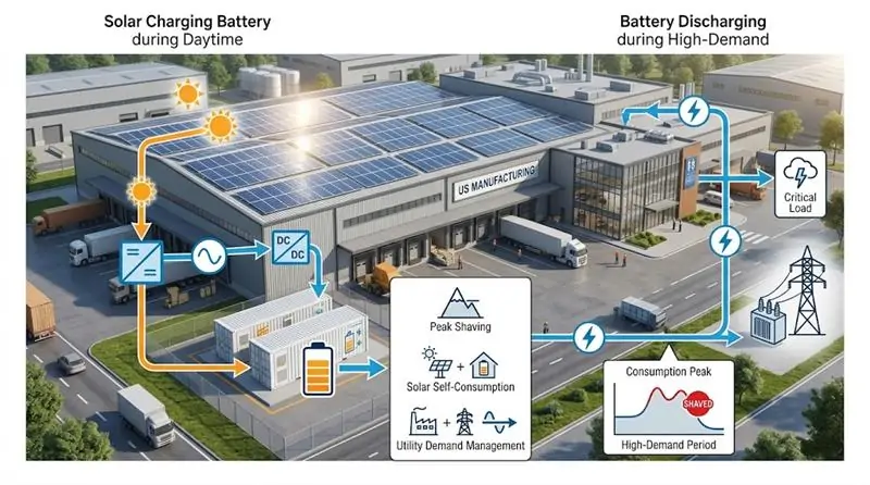
5.1 Solution A: Factory Solar + Storage with Grid Peak Shaving
A typical factory configuration combines rooftop or ground-mounted PV, battery storage, the utility grid, and facility loads.
During periods of strong solar generation, PV power can serve the facility loads and charge the battery. During selected peak periods, the battery can discharge to reduce grid import.
Where utility rules require zero export, CT-based metering and anti-reverse-power control can be used to monitor facility power flow and control battery/PV output accordingly.
This approach is particularly relevant to U.S. facilities operating under demand charges or time-varying electricity rates.
5.2 Solution B: Off-Grid Solar-Diesel-Storage Microgrid
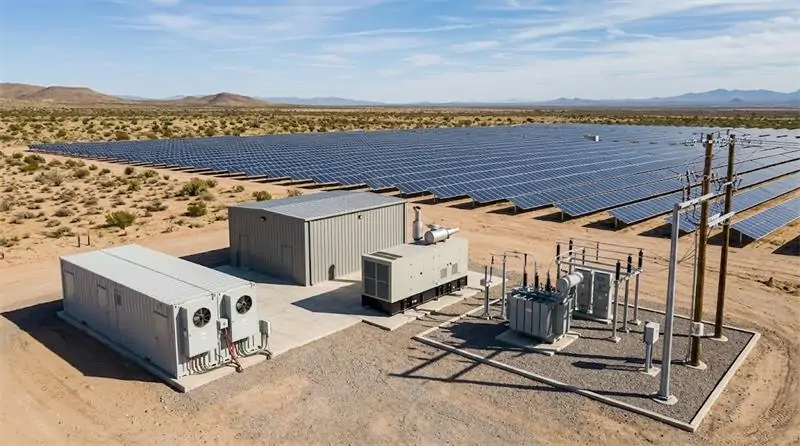
Remote industrial sites cannot always depend on a strong utility connection. Mining operations, oilfield sites, remote farms, construction projects, and island facilities may need a combination of PV, batteries, and diesel generation.
In this architecture, the battery can absorb renewable generation and provide power during periods when solar output is insufficient. The diesel generator can operate as an additional dispatchable source.
GEYA’s larger microgrid systems are designed to coordinate PV, battery, grid and diesel-generator sources through integrated EMS control.
The actual fuel savings depend on the generator operating point, load profile, PV resource, battery capacity, and control strategy. Therefore, fuel-saving percentages should be calculated from project-specific operating data rather than assumed as a fixed value.
5.3 Solution C: UPS-Grade Critical Power Protection
Facilities with sensitive loads may not need backup power for the entire building.
Instead, engineers can create a dedicated critical-load bus for selected equipment such as servers, automation systems, control systems, refrigeration equipment, communication equipment, and other essential machinery.
The ESS then prioritizes these loads during a utility interruption.
Transfer performance depends on the selected equipment and operating mode. For example, GEYA’s GYS 250H specifies active transfer at 0 ms and passive transfer below 10 ms, while other models have different electrical architectures and specifications.
Therefore, EPC contractors should always match the required transition performance with the actual load and equipment requirements rather than assuming every ESS has identical transfer behavior.
6. Why Source C&I Energy Storage Systems from GEYA?
For commercial and industrial energy storage, product selection is only one part of the procurement decision. EPC contractors and system integrators also need a supplier capable of supporting system engineering, customization, communication integration, manufacturing, documentation, and project delivery.
6.1 Integrated Electrical Engineering Capability
GEYA develops and supplies energy storage and electrical products for residential, commercial, industrial, and microgrid applications.
Its C&I ESS portfolio ranges from compact three-phase all-in-one systems to 100 kW, 150 kW, and 250 kW-class integrated microgrid systems.
6.2 Multi-Source Energy Integration
Modern C&I projects increasingly require more than battery storage.
GEYA’s larger integrated systems are designed to coordinate PV, battery storage, utility power, diesel generators, and facility loads through integrated control functions.
This makes the system architecture suitable for both grid-connected energy management and more complex microgrid applications.
6.3 OEM/ODM and Project-Based Engineering
C&I energy storage projects often require different battery capacities, PV configurations, communication interfaces, operating strategies, and cabinet configurations.
For EPC contractors and project developers, the ability to discuss these requirements directly with the manufacturer can be important when developing a project-specific solution.
Instead of selecting equipment based only on nominal kW and kWh ratings, the engineering review should cover:
- Load profile and critical loads
- PV capacity and string configuration
- Battery voltage and usable energy
- Grid voltage and frequency
- Backup operating mode
- Diesel generator integration
- EMS communication requirements
- Site temperature and altitude
- Protection and enclosure requirements
- Expansion and parallel-operation requirements
6.4 Explore GEYA’s Commercial & Industrial Energy Storage Portfolio
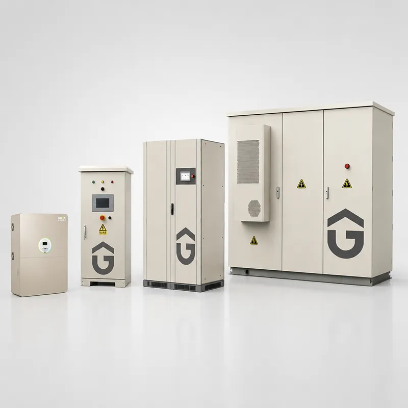
To compare available C&I ESS models, battery configurations, power ratings, PV input capabilities, and application scenarios, visit the GEYA Commercial & Industrial Energy Storage System category.
7. Conclusion: Build the ESS Around the Project, Not the Other Way Around
A commercial and industrial energy storage system should never be sized simply by choosing the largest available battery.
The correct system begins with the project’s actual electrical behavior.
7.1 Final C&I ESS Sizing Checklist
- Have you collected interval load data?
- Have you identified the facility’s maximum demand?
- Have you separated critical loads from non-critical loads?
- Have you determined the required backup duration?
- Have you reviewed the utility’s TOU and demand-charge structure?
- Have you evaluated the facility’s PV generation profile?
- Have you checked PV voltage and MPPT requirements?
- Have you confirmed battery voltage and usable energy?
- Have you evaluated motor-starting and transient loads?
- Do you need zero-export or anti-reverse-power control?
- Will the system need diesel-generator integration?
- Does the project require grid-connected, off-grid, or hybrid operation?
- Will the system need future parallel expansion?
7.2 Get a Project-Specific C&I ESS Design
Every commercial and industrial site has a different load profile, utility tariff, solar resource, operating schedule, and backup requirement.
That is why the most effective way to select an ESS is to start with the project data and work backward to the required PCS power, battery capacity, PV capacity, and control architecture.
Have an upcoming commercial or industrial energy storage project? Share your load profile, required backup duration, PV capacity, utility voltage, and project application with the GEYA engineering team to discuss a suitable system configuration.
Contact GEYA Engineering Team →
You can also review the complete GEYA Commercial & Industrial Energy Storage System portfolio to compare available solutions.
Technical Reference: Download the GEYA All-in-One Solar ESS Hybrid Inverter Catalog for additional product information and technical specifications.