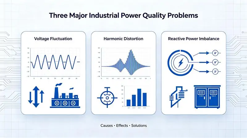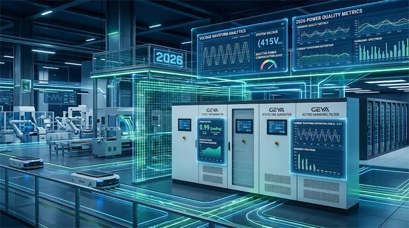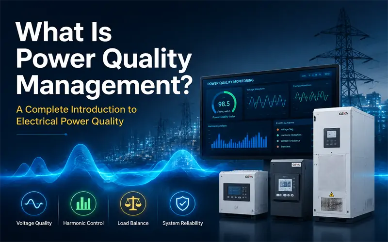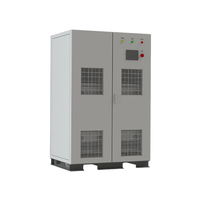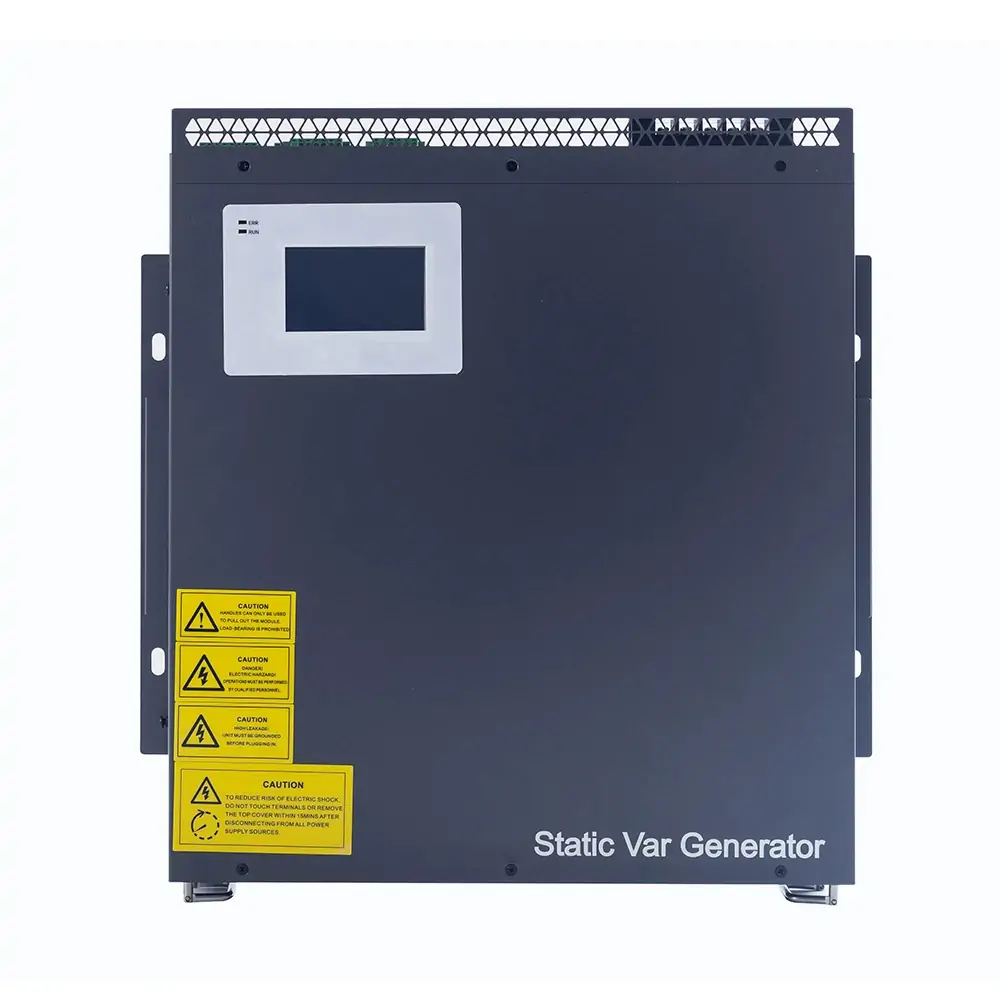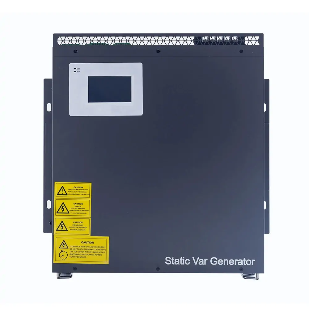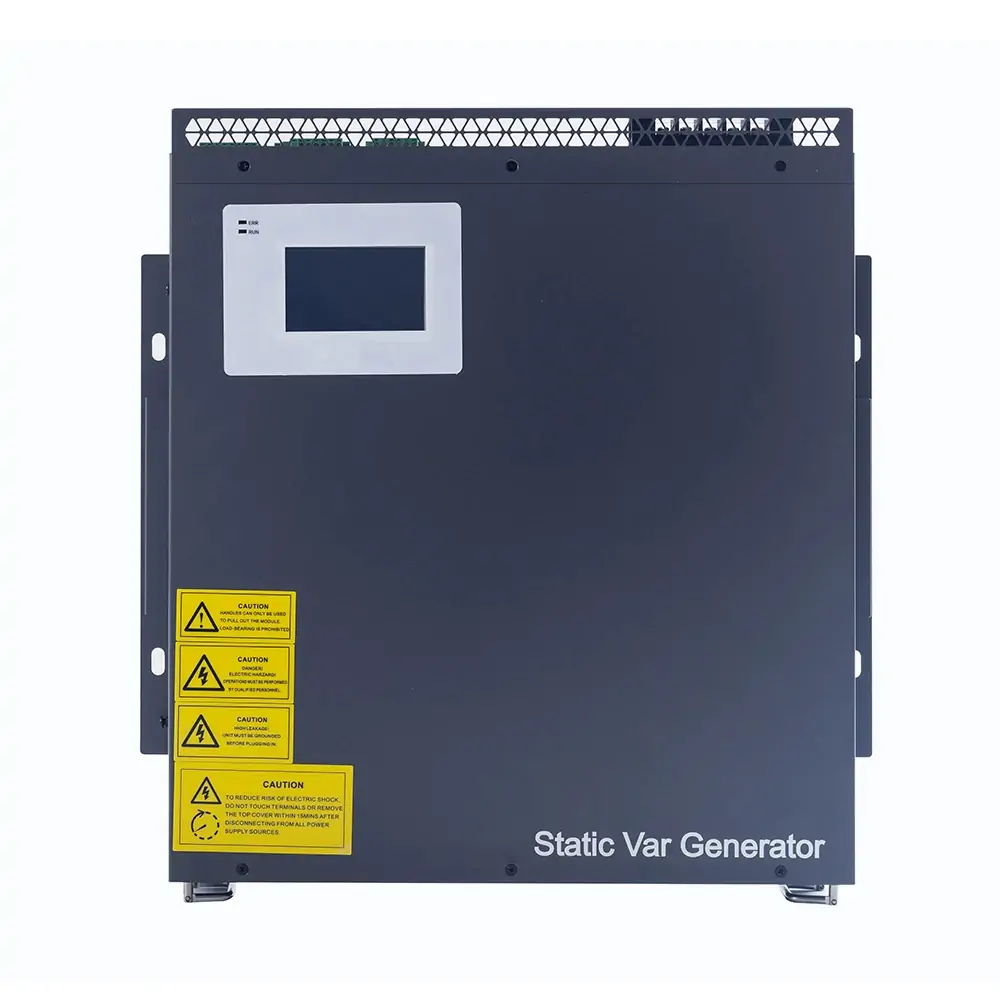
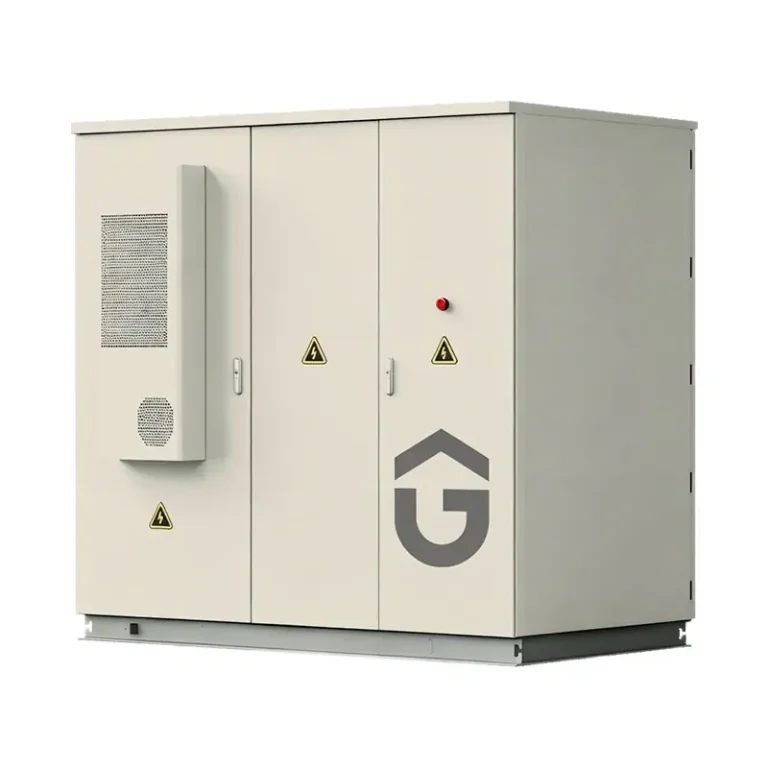
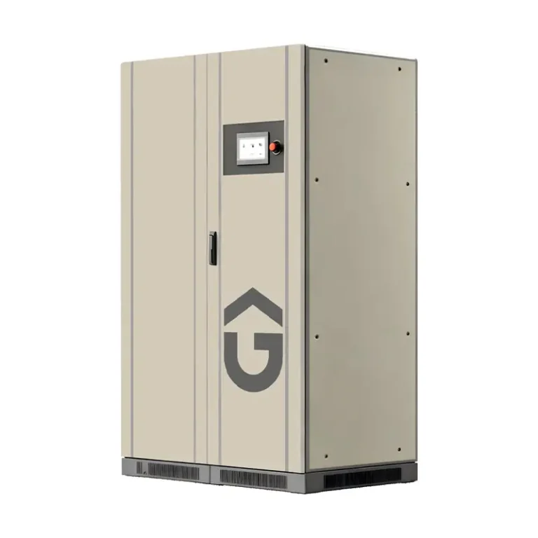
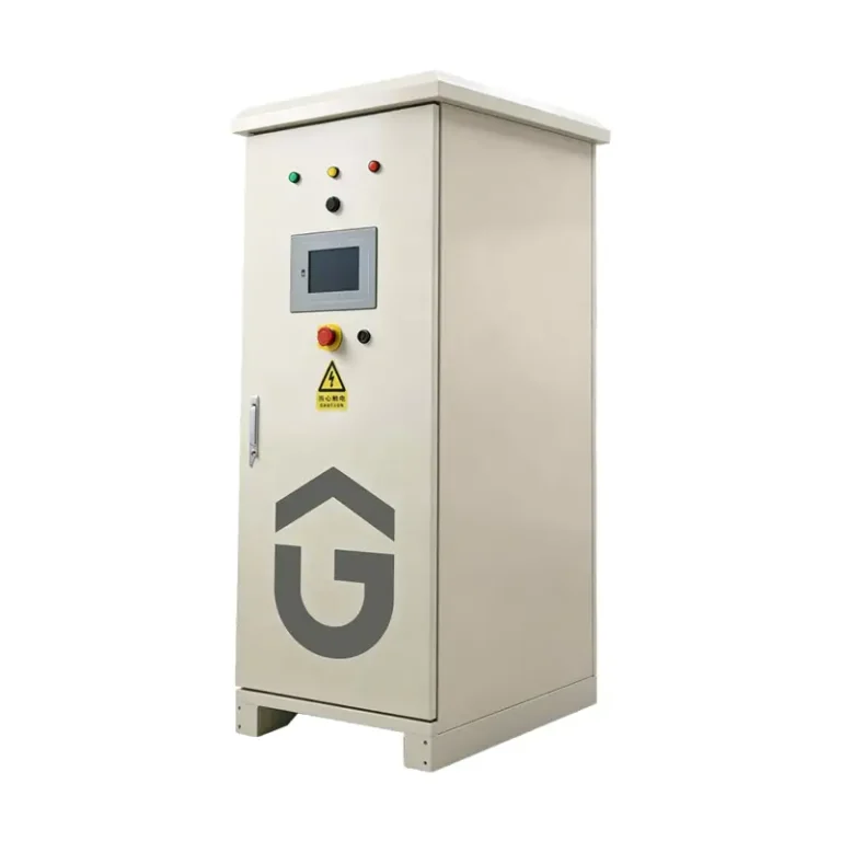
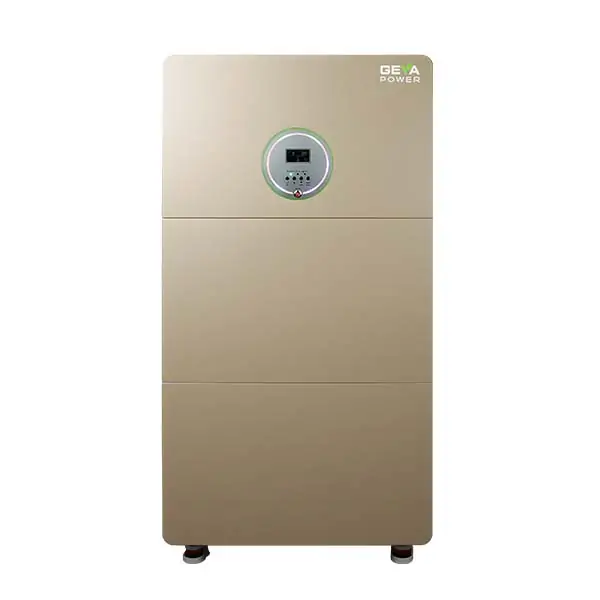
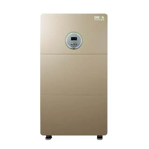
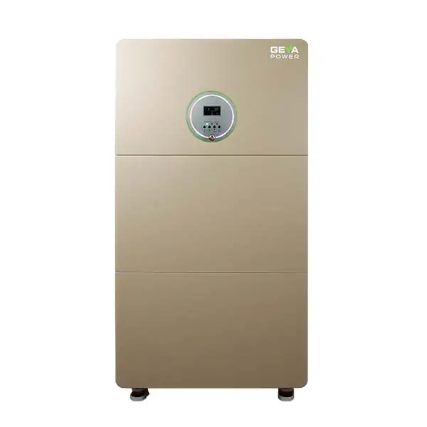
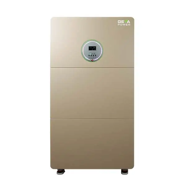
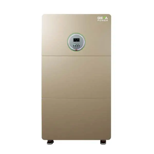
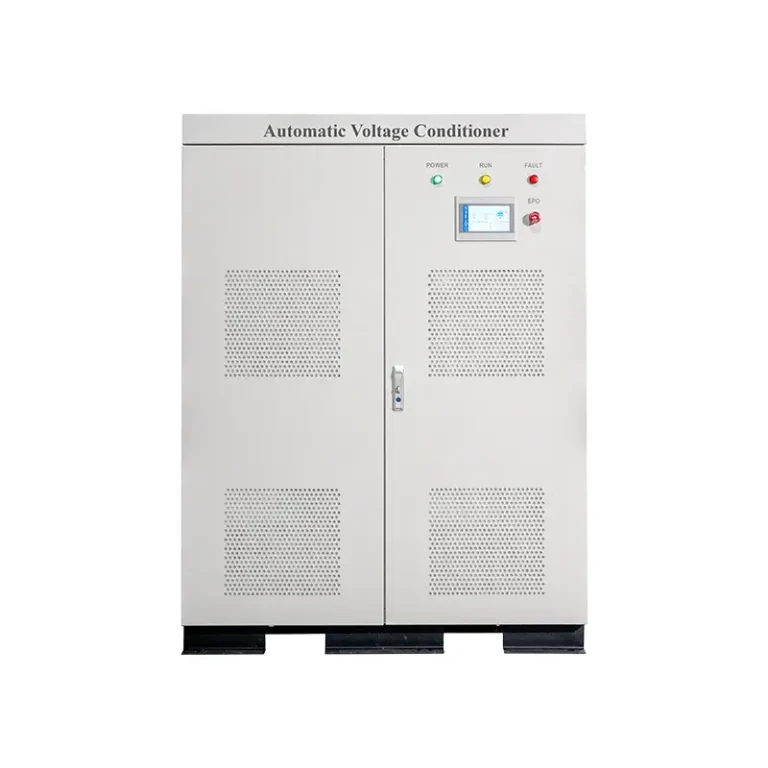
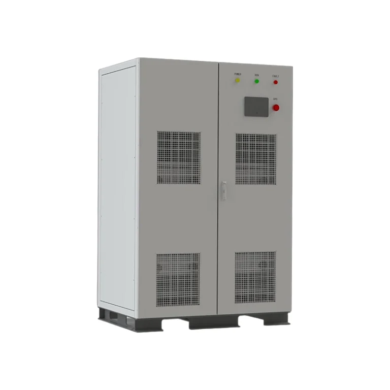
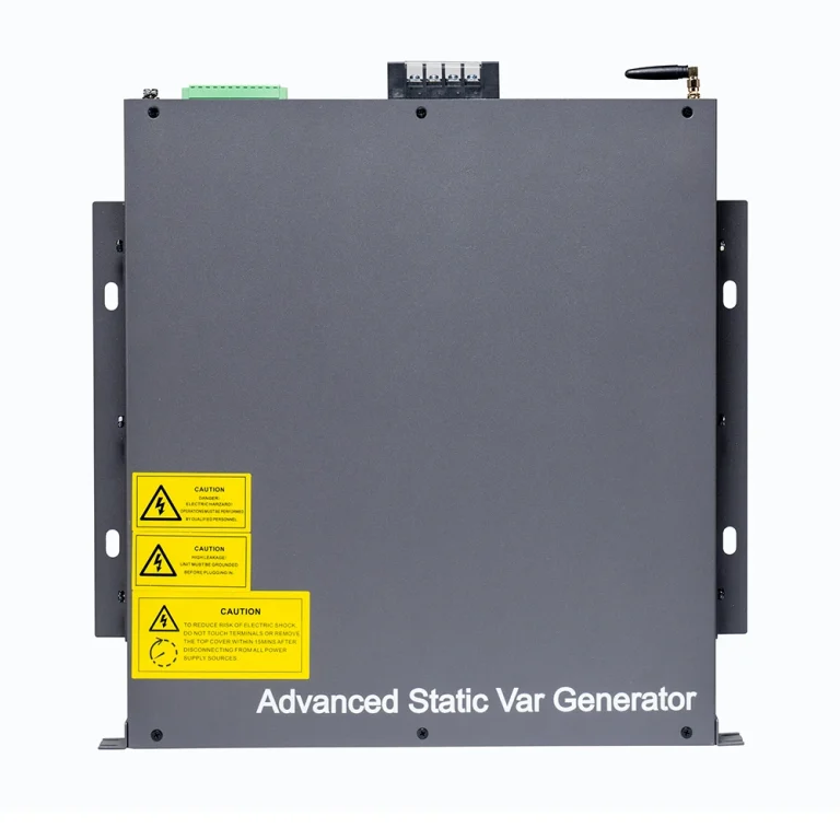
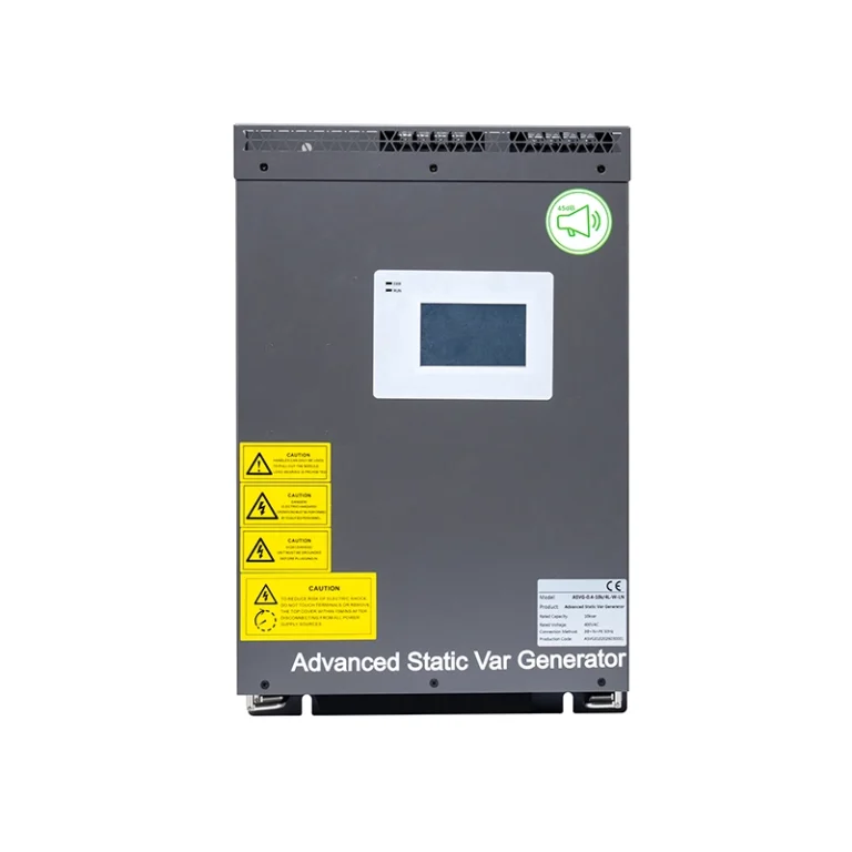
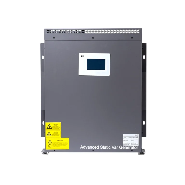
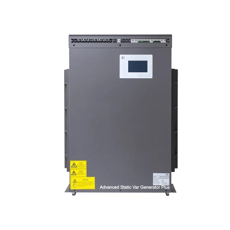
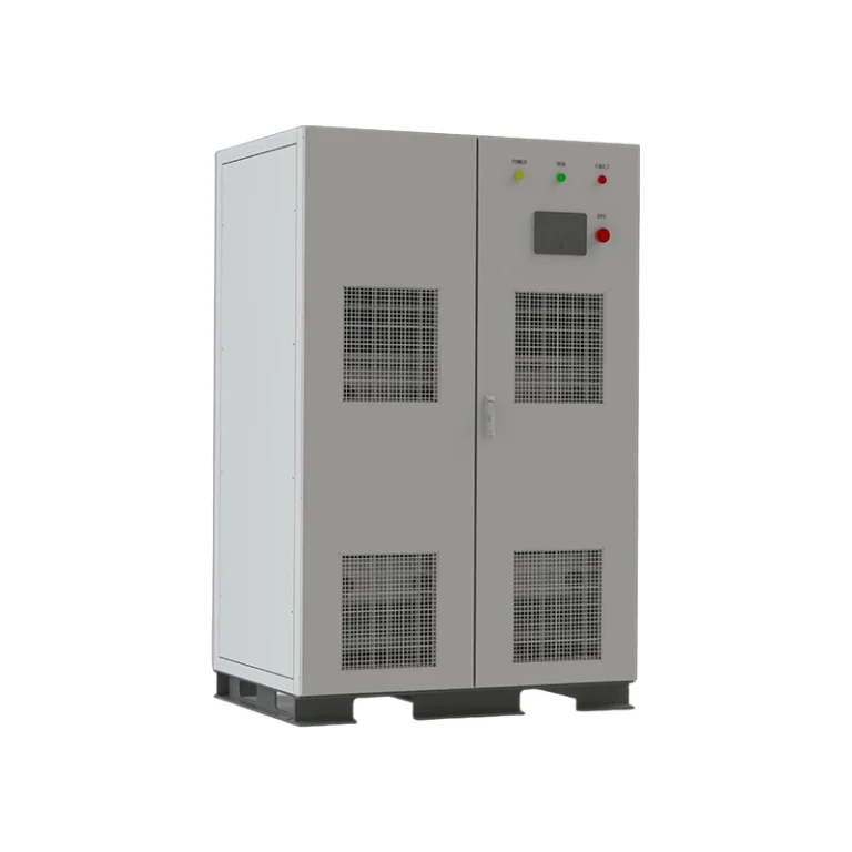
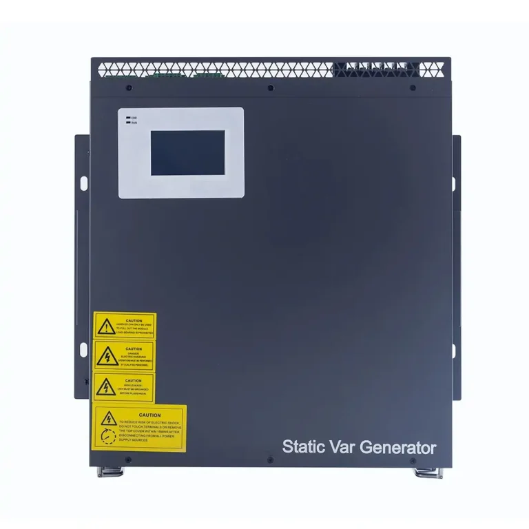
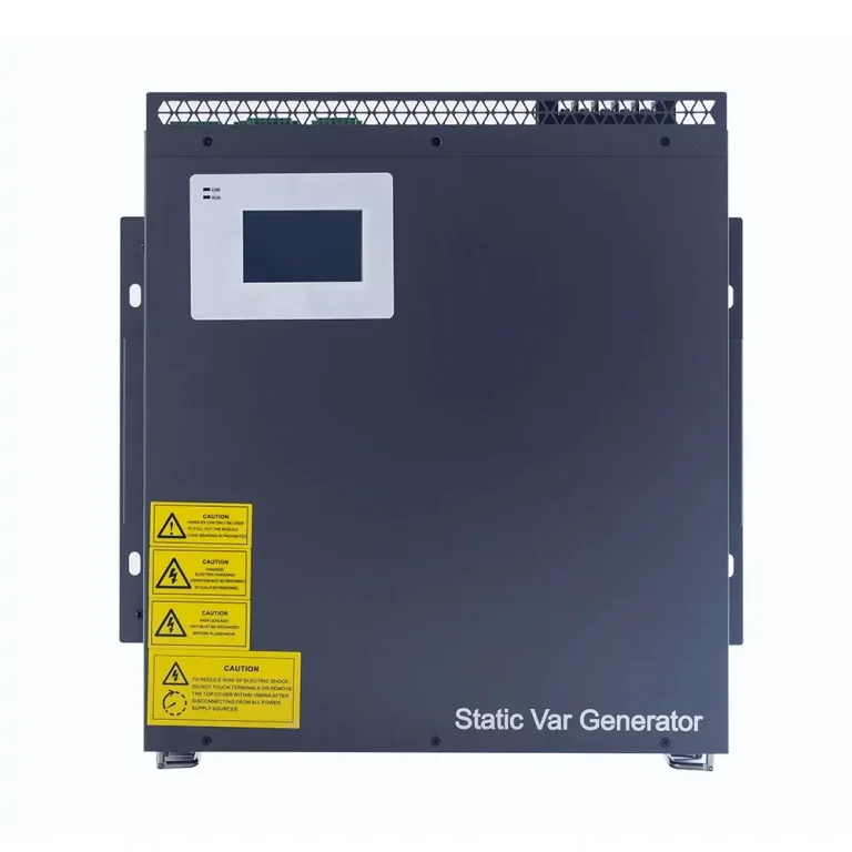



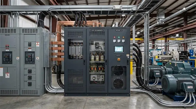
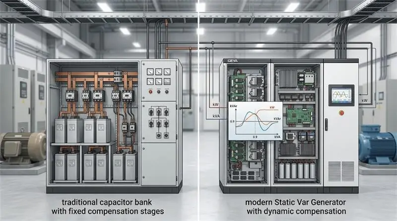
A Static Var Generator (SVG) provides a dynamic solution. Instead of relying on fixed compensation steps, an SVG continuously monitors electrical conditions and generates the required compensating current in real time.
GEYA’s GY-SVG series uses a voltage source converter (VSC), DSP+CPLD full-digital control, three-level topology, and modular architecture to provide dynamic reactive power compensation. According to the GEYA Power Quality Product Manual, the GY-SVG series provides a transient response of less than 50 μs and a full response time of less than 10 ms, with reactive power compensation capability of ≥99%.
Introduction: When Reactive Power Starts Working Against Your Electrical System
In a busy industrial facility, electrical problems rarely arrive with a warning.
A large motor starts. A compressor changes operating conditions. Welding equipment comes online. Production demand shifts again. Within seconds, reactive power demand can move significantly across the electrical system.
The result may appear in places that are easy to overlook: a lower power factor, higher current, additional transformer loading, increased distribution losses, or voltage that becomes less stable when large loads change suddenly.
For facility engineers and electrical maintenance teams, the challenge is not simply supplying enough electricity. It is keeping the electrical system stable while the load keeps moving.
This is where a Static Var Generator (SVG) can make a fundamental difference.
Instead of switching fixed capacitor stages according to predefined steps, an SVG continuously monitors electrical conditions and dynamically generates the reactive current required by the system. GEYA’s GY-SVG series provides a transient response of less than 50 μs and a full response time of less than 10 ms, helping industrial facilities respond to rapidly changing reactive power demand with much greater precision.
In the sections below, we will explain how SVG technology works, how to select the right GEYA SVG for different applications, what determines equipment performance, and how to keep an SVG operating reliably for the long term.
1. SVG Core Working Principle and Key Advantages
What Is a Static Var Generator?
A Static Var Generator, commonly abbreviated as SVG, is a power-electronic device used for dynamic reactive power compensation.
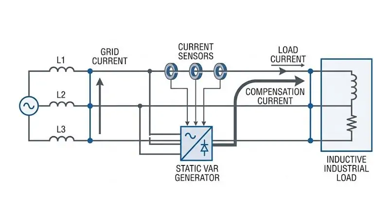
The basic concept is straightforward. The SVG is connected to the electrical system in parallel with the load. It detects the electrical condition of the system and generates a compensation current with the required magnitude and phase.
GEYA’s GY-SVG working principle uses a voltage source converter (VSC) connected to the power grid through a filter. By adjusting the amplitude and phase of the converter’s AC-side output voltage, the SVG dynamically compensates reactive power in the grid.
In practical terms, the process can be understood as:
Monitor → Detect Reactive Power Demand → Calculate Compensation → Generate Compensation Current → Improve Power Factor
Why Response Speed Matters
Industrial loads do not always behave smoothly. A motor can start, a compressor can switch operating conditions, or a welding process can suddenly increase electrical demand.
If compensation reacts too slowly, the electrical system may temporarily experience poor power factor or voltage disturbances before the compensation equipment catches up.
GEYA GY-SVG specifies a transient response time of less than 50 μs and a full response time of less than 10 ms.
This fast response allows the SVG to dynamically follow changing reactive power demand and is particularly useful for impact and fluctuating loads.
In other words, the system does not simply wait for the next capacitor stage to switch. It continuously adjusts the compensation output according to actual electrical conditions.
SVG vs. Traditional Capacitor Banks
| Feature | Static Var Generator (SVG) | Traditional Capacitor Bank |
|---|---|---|
| Compensation method | Power-electronic dynamic compensation | Fixed capacitor stages |
| Response | Dynamic, millisecond-level response | Step-based switching response |
| Changing loads | Highly adaptable | More dependent on load characteristics |
| Over-compensation risk | Precisely controlled according to demand | Higher under rapidly changing conditions |
| Reactive compensation | Bidirectional dynamic compensation | Primarily capacitor-based compensation |
| Expansion | Modular parallel expansion | Requires additional capacitor stages |
Traditional capacitor banks are not automatically “bad” technology. They remain practical in applications with relatively stable reactive loads and straightforward compensation requirements.
The difference is that SVG technology is designed for electrical systems where the compensation demand changes quickly and frequently.
What Can GEYA GY-SVG Do?
According to the GEYA product manual, the GY-SVG supports selectable operating modes for reactive power compensation and reactive power compensation plus three-phase unbalance compensation.
The standard GY-SVG provides:
- Reactive power compensation rate ≥99%
- Post-compensation unbalance degree ≤5% where the unbalance compensation function is supported
- Transient response <50 μs
- Full response <10 ms
- Overall efficiency ≥97%
- 1.2 times rated overload for 60 seconds
- Unlimited parallel operation
- DSP+CPLD full-digital control
- Three-level topology
- Two external current sampling channels
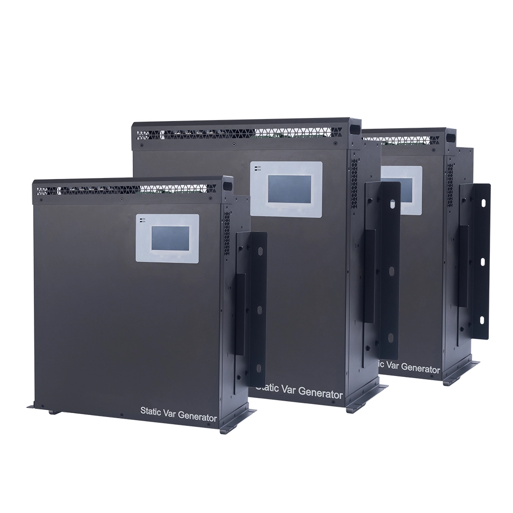
- Rack-mounted and wall-mounted installation
The standard GY-SVG platform covers AC 220 V, 380 V, 500 V, 690 V, and 800 V systems, with voltage tolerances and compensation capacities depending on the specific voltage platform.
For US engineering projects, it is important not to select a voltage platform simply because the nominal facility voltage looks similar. For example, many US industrial facilities use 480 V distribution systems, while the GEYA catalog lists 500 V rather than a dedicated 480 V platform. The actual project voltage, transformer arrangement, wiring configuration, CT location, and compensation requirement should therefore be confirmed with GEYA before final selection.
2. How to Select the Right GEYA SVG for Your Application
Choosing an SVG should never start with the question, “How many kvar do I want?”
A professional selection process starts with the electrical system itself.
Step 1: Identify the Main Electrical Problem
First determine whether the primary issue is reactive power, harmonics, voltage instability, three-phase imbalance, or a combination of several problems.
If the main problem is low power factor and rapidly changing reactive power demand, SVG is often the appropriate technology.
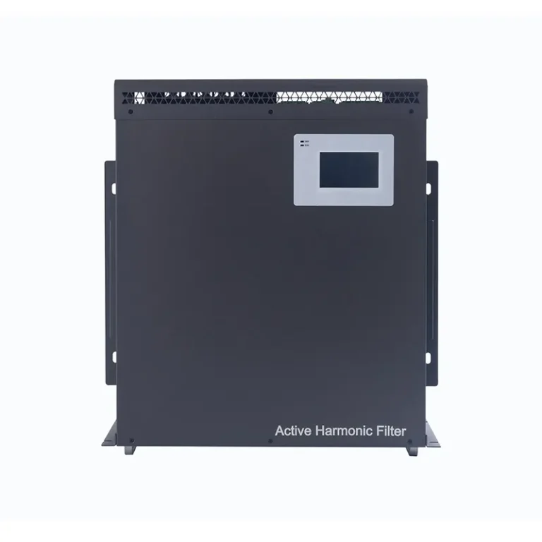
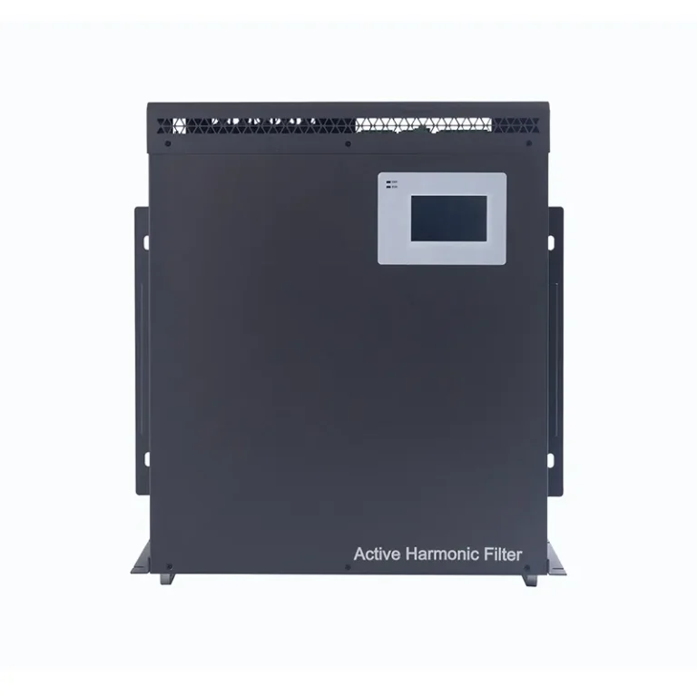
If the facility also has significant harmonic distortion, an integrated power quality solution may be more appropriate. GEYA offers Active Harmonic Filter (AHF) and Advanced Static Var Generator (ASVG) technologies for applications where harmonic compensation is also required.
For facilities where voltage regulation itself is the primary problem, an Automatic Voltage Control (AVC) solution may need to be considered.
Step 2: Determine the System Voltage
Voltage compatibility is one of the first technical filters when selecting an SVG.
GEYA GY-SVG supports the following main voltage platforms:
| Voltage Platform | Operating Voltage Range | Typical Catalog Capacity Range |
|---|---|---|
| 220 V | AC 220 V (-20% to +20%) | 3 / 5 / 7 / 10 / 17 / 25 / 37 / 50 / 75 kvar |
| 380 V | AC 380 V (-20% to +20%) | 5 / 10 / 15 / 20 / 35 / 50 / 75 / 100 / 150 kvar |
| 500 V | AC 500 V (-20% to +20%) | 90 kvar |
| 690 V | AC 690 V (-20% to +15%) | 120 kvar |
| 800 V | AC 800 V (-20% to 850 V max) | 150 kvar |
These figures are based on the GEYA Power Quality Product Manual. Final project configurations should always be confirmed against the latest technical quotation and application requirements.
Step 3: Calculate the Required Compensation Capacity
The required SVG capacity should be calculated from actual reactive power demand rather than simply selecting the largest available model.
Useful engineering inputs include:
- Existing power factor
- Target power factor
- Active power demand
- Maximum reactive power demand
- Minimum and maximum load conditions
- Load fluctuation characteristics
- Future load expansion
For a basic engineering estimate, the required compensation can be related to the difference between the existing and target power factor:
Qc = P × (tan φ₁ − tan φ₂)
where:
- Qc = required reactive compensation capacity
- P = active power demand
- φ₁ = existing power factor angle
- φ₂ = target power factor angle
This calculation provides an engineering starting point, but actual selection should also consider dynamic load behavior, measurement results, CT installation location, system voltage, wiring configuration, and future expansion.
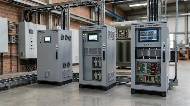
Step 4: Decide Between Standard SVG, SVG-PLUS and SVG-SiC
GEYA provides different SVG platforms for different performance requirements.
GY-SVG — Standard Dynamic Reactive Power Compensation
The standard GY-SVG is designed for dynamic reactive power compensation and can also support three-phase unbalance compensation depending on the selected model and configuration.
It provides ≥99% reactive compensation capability, <50 μs transient response, <10 ms full response, ≥97% overall efficiency, modular parallel operation, dual external CT channels, and rack/wall-mounted installation.
Explore GEYA GY-SVG Static Var Generator →
GY-SVG-PLUS — Higher-Specification SVG
For applications requiring additional neutral-line filtering and enhanced electromagnetic compatibility, the GY-SVG-PLUS adds several upgraded functions.
The catalog specifies neutral-line zero-sequence current filtering capability up to three times the phase-line filtering capability. It also provides Class A EMC performance for radiated emission and conducted emission testing.
The GY-SVG-PLUS is available on the 220 V and 380 V platforms listed in the catalog, with rated capacities of 37/50 kvar for 220 V and 75/100 kvar for 380 V.
GY-SVG-SiC — High-Efficiency SiC Platform
When efficiency, power density, and advanced power-device technology become priorities, the GY-SVG-SiC provides a higher-performance option.
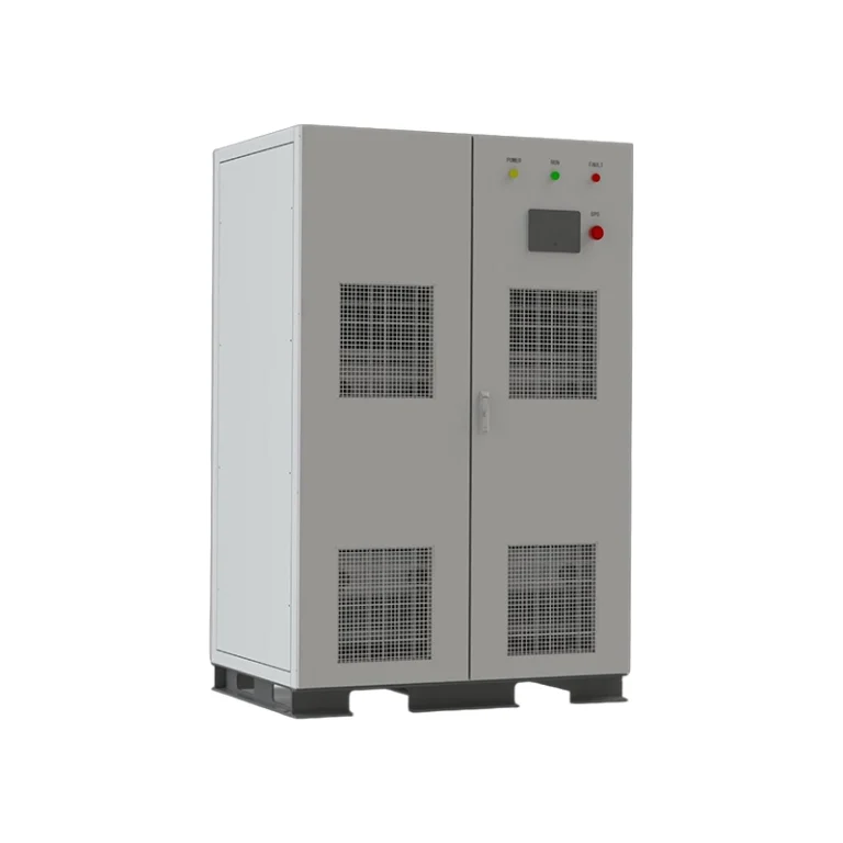
The GEYA catalog specifies peak efficiency above 98.5%, a 30 kHz switching frequency, high-density modular architecture, and up to eight modules in a single cabinet with a maximum capacity of 800 kvar.
The GY-SVG-SiC also supports ≥99% reactive compensation, post-compensation unbalance of ≤5%, neutral-line filtering capacity three times that of the phase line, and 100% current-limiting output.
3. Core Components: What Actually Determines SVG Performance?
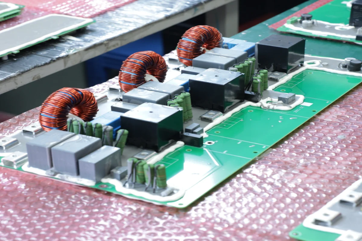
An SVG is not simply a cabinet containing power modules. Its real performance depends on the interaction between the power semiconductor stage, control system, sensing system, filter, thermal design, and protection architecture.
Power Module
The power module is responsible for converting electrical energy into precisely controlled compensation current.
GEYA’s standard SVG architecture uses a three-level topology. The GY-SVG-SiC version uses silicon carbide power devices to reduce module losses and increase power density.
SiC becomes particularly valuable in demanding applications because its higher switching capability and voltage withstand characteristics can support higher-frequency operation, reduced output ripple current, and improved thermal and EMC design.
However, the most advanced semiconductor technology is not automatically the best choice for every project. Engineers should balance efficiency, required capacity, installation space, operating conditions, and project budget.
Digital Control System
The control system is the “brain” of the SVG.
GEYA GY-SVG products use a DSP+CPLD full-digital control core, advanced reactive power detection algorithms, and PWM control strategies.
The control system continuously evaluates the electrical condition and determines how the converter should generate the required compensation current.
This is one of the fundamental differences between dynamic SVG technology and traditional fixed compensation equipment.
Current Sampling System
Accurate measurement is essential because compensation quality depends on the controller knowing what is actually happening in the electrical system.
GEYA GY-SVG provides two external current sampling channels. According to the catalog, these channels support different configurations including low-voltage-side sampling with low-voltage-side compensation, high-voltage-side sampling with low-voltage-side compensation, and reactive-component compensation.
For an engineering project, CT placement should therefore be treated as part of the system design rather than a minor installation detail.
Cooling and Thermal Management
Power electronics generate heat. As compensation capacity increases, thermal management becomes increasingly important.
GEYA GY-SVG, GY-SVG-PLUS and GY-SVG-SiC use forced-air cooling and independent air-duct structures.
The catalog specifies an operating ambient temperature of -10°C to +50°C. Above 40°C, capacity derating does not exceed 30% according to the catalog specifications.
The standard environmental conditions also include relative humidity of ≤90% with no surface condensation at a monthly minimum temperature of 25°C, and pollution degree ≤ Class III.
Protection System
Industrial compensation equipment must continue operating in an environment where electrical disturbances are possible.
GEYA SVG protection functions include protection against overload, software and hardware overcurrent, grid overvoltage and undervoltage, power supply failure, overtemperature, and frequency abnormalities. The higher-specification models additionally include functions such as short-circuit and resonance protection.
The catalog also specifies a rated overload capability of 1.2 times for 60 seconds.
4. Practical SVG Maintenance Tips for Long-Term Operation
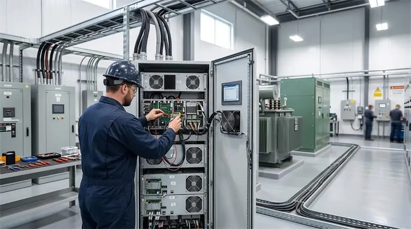
Installing an SVG is only the beginning. Long-term performance depends heavily on installation quality, operating environment, thermal management, and routine inspection.
Tip 1: Keep the Airflow Path Clean
Dust accumulation can reduce airflow and increase thermal stress on power electronics.
During routine maintenance, inspect ventilation openings, fans, air ducts, and cabinet airflow paths. If the installation environment is dusty, inspection intervals should be shortened according to actual site conditions.
Tip 2: Monitor Operating Temperature
Temperature is one of the easiest indicators of abnormal operating conditions.
If an SVG begins operating at a noticeably higher temperature than normal, check airflow, ambient temperature, fan operation, cabinet ventilation, and load conditions before the problem develops into a shutdown.
Tip 3: Inspect Electrical Connections
Loose electrical connections can create localized heating and unstable operation.
During scheduled maintenance, inspect power terminals, grounding connections, CT wiring, communication connections, and other critical electrical interfaces according to the manufacturer’s maintenance procedures.
Tip 4: Check CT Installation and Sampling Signals
An SVG depends on accurate current information. Incorrect CT orientation, poor wiring, or an unsuitable sampling location can affect compensation performance.
If compensation appears abnormal after commissioning or maintenance work, verify the CT configuration before assuming that the SVG power module has failed.
Tip 5: Monitor Power Factor Before and After Compensation
Do not evaluate an SVG only by whether its display shows “running.”
Compare electrical parameters before and after compensation, including power factor, reactive power, current, voltage, and load behavior.
This provides a more meaningful picture of whether the compensation system is actually delivering the expected result.
Tip 6: Pay Attention to Repeated Protection Events
A protection event is not always a problem with the SVG itself.
Repeated overcurrent, overtemperature, voltage, frequency, or other protection events may indicate an underlying issue in the electrical system, installation environment, load behavior, or configuration.
Do not repeatedly reset the equipment without identifying the root cause.
Tip 7: Plan for Future Expansion
Industrial electrical systems rarely remain unchanged for years.
Production capacity may increase, new motors may be added, or renewable energy and other power-electronic equipment may be introduced later.
GEYA’s modular SVG architecture supports parallel operation, allowing engineers to consider staged capacity expansion instead of designing every project around a single fixed-capacity installation.
5. Conclusion: Is SVG the Right Reactive Power Compensation Solution for Your Facility?
A Static Var Generator is more than a modern replacement for a capacitor bank. It is a dynamic power-electronic compensation technology designed for electrical systems where reactive power demand changes continuously.
For industrial facilities with motors, compressors, pumps, welding equipment, transformers, and other fluctuating loads, the ability to respond quickly can make a meaningful difference to power factor performance, electrical loading, and overall power quality.
GEYA’s GY-SVG platform provides a scalable range of solutions, from the standard GY-SVG to the higher-specification GY-SVG-PLUS and the high-efficiency GY-SVG-SiC platform.
The key specifications include:
- Reactive power compensation capability ≥99%
- Transient response <50 μs
- Full response <10 ms
- Overall efficiency ≥97% for the standard SVG platform
- Peak efficiency above 98.5% for GY-SVG-SiC
- Modular parallel operation
- DSP+CPLD full-digital control
- Three-level topology
- Rack-mounted and wall-mounted installation options
- Multiple voltage platforms from 220 V to 800 V depending on model
However, selecting the right SVG is ultimately an engineering decision. The correct solution depends on system voltage, reactive power demand, load fluctuation, CT configuration, environmental conditions, required functions, future expansion, and project objectives.
If your facility is experiencing low power factor, fluctuating reactive power demand, voltage instability, or excessive electrical loading, GEYA can help evaluate the application and identify the appropriate SVG configuration.
Explore GEYA Power Quality Management Solutions →
View GY-SVG Static Var Generator →
Need help selecting the right SVG capacity for your project? Contact GEYA with your system voltage, load capacity, existing power factor, target power factor, and load profile for a project-specific recommendation.