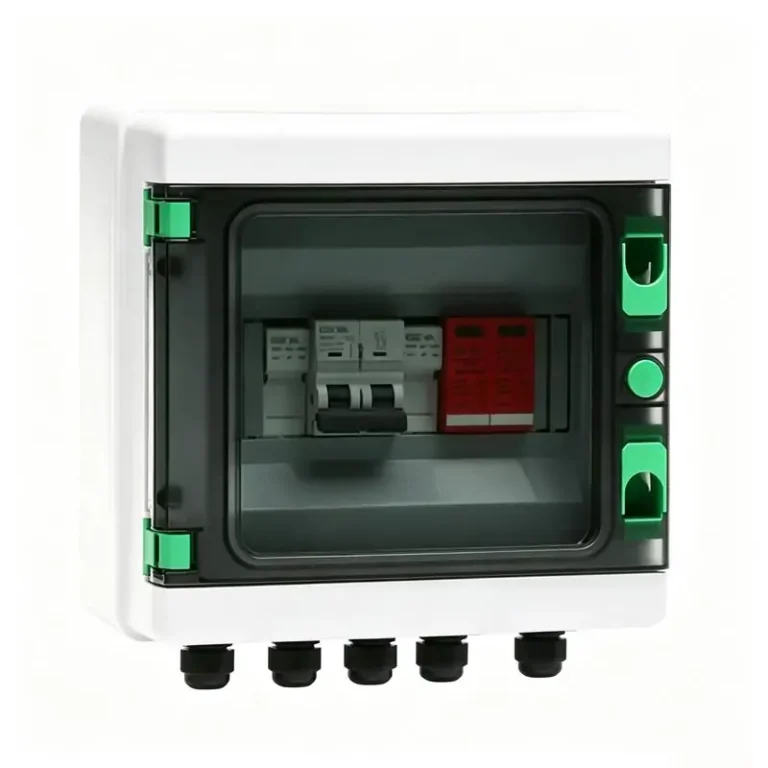
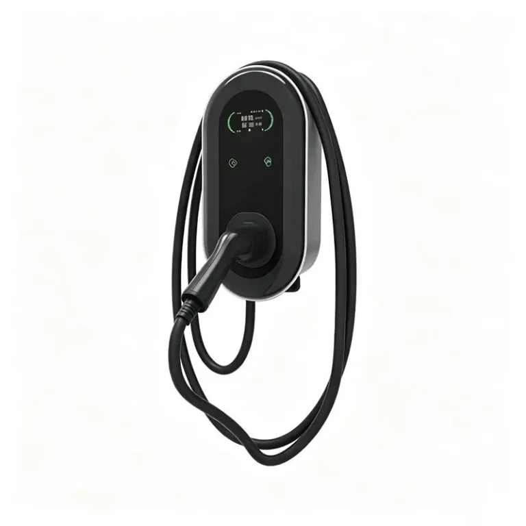
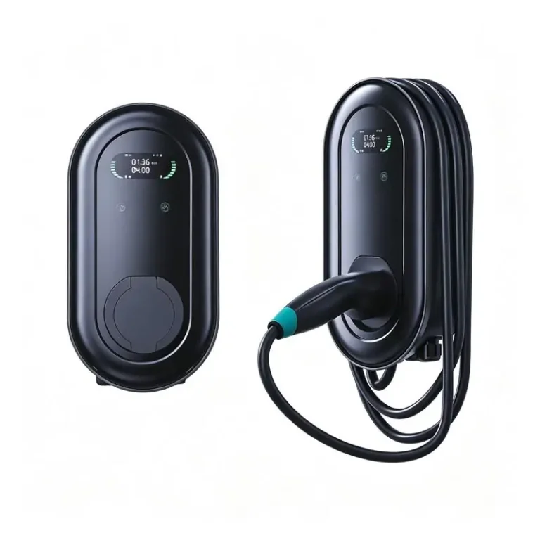
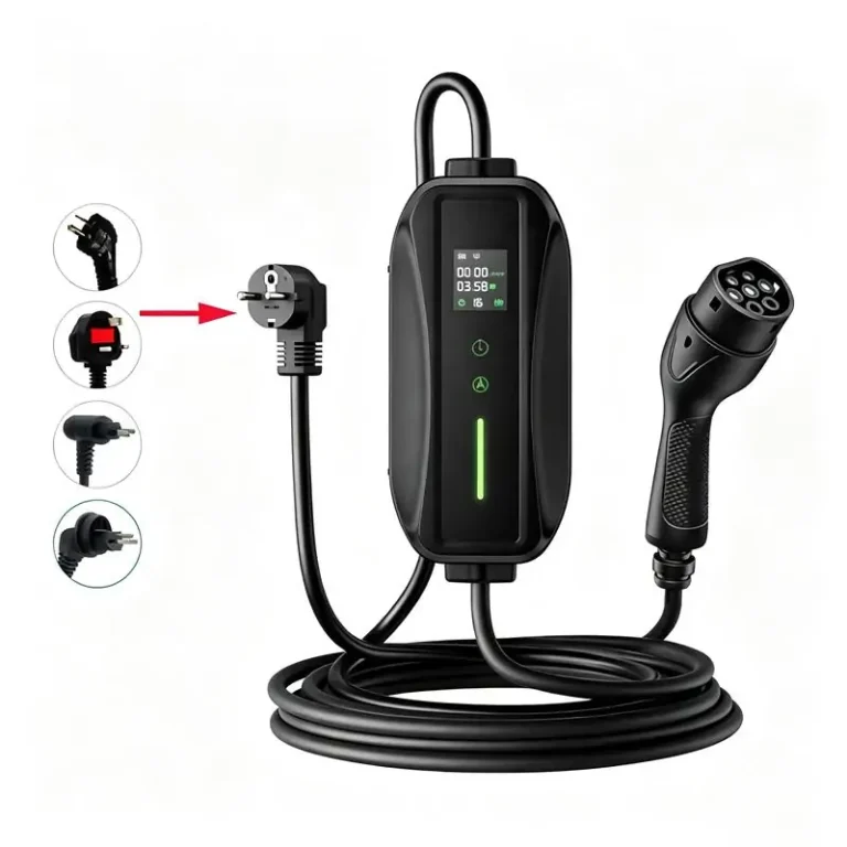



However, variable frequency drives (VFDs), uninterruptible power supplies (UPS), robotics,
HVAC systems, LED lighting, and electric vehicle (EV) chargers can introduce harmonic distortion,
reactive power demand, voltage fluctuations, and phase imbalance into electrical distribution systems.These problems can increase electrical losses, reduce usable distribution capacity, trigger
equipment malfunctions, and contribute to unexpected production interruptions. For facility
managers and electrical engineers, effective power quality management is therefore not simply
a matter of installing compensation equipment. It requires a coordinated approach to measurement,
diagnosis, mitigation, and ongoing performance verification.This guide explains the major power quality challenges facing factories and commercial buildings
in the United States, compares practical mitigation technologies, and outlines a measurement-led
approach to improving electrical system performance.
1. Why Power Quality Matters in Modern Facilities
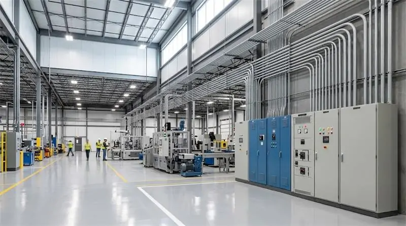
Industrial automation and building electrification are changing the way electricity is consumed.
Modern facilities operate an increasing number of electronically controlled loads, while rooftop
solar photovoltaic (PV) systems, battery energy storage, and EV charging infrastructure introduce
additional operating conditions that electrical engineers must consider.
In the United States, facilities commonly operate at distribution voltages such as 480Y/277 V
and 208Y/120 V, depending on the building type and electrical design. Within these systems,
nonlinear loads and rapidly changing demand can create power quality problems that conventional
distribution equipment alone may not adequately address.
1.1 The Hidden Cost of Electrical Disturbances
Poor power quality does not always cause an immediate equipment failure. Its effects may develop
gradually through additional heating, insulation stress, nuisance tripping, reduced equipment
availability, and inefficient use of electrical infrastructure.
In a manufacturing plant, a brief voltage disturbance may interrupt a PLC-controlled production
sequence, stop a robotic workstation, or require a production line to be restarted. In a commercial
building, harmonic currents and uneven phase loading may increase neutral conductor heating,
complicate electrical maintenance, or reduce the available capacity of distribution equipment.
The financial impact depends on the facility, the affected process, the disturbance duration,
and the equipment involved. A useful power quality strategy therefore begins by identifying
which electrical problems are actually occurring and how they affect business operations.
1.2 From Reactive Maintenance to Proactive Power Quality Management
Traditional maintenance often begins after a breaker trips, a transformer overheats, or production
equipment unexpectedly shuts down. A proactive approach combines electrical measurements,
engineering analysis, appropriate mitigation equipment, and continuous monitoring where needed.
The objective is to identify disturbances before they become costly operational problems,
select technologies that address the measured causes, and verify their effectiveness after installation.
2. Four Common Power Quality Problems and Their Operational Risks
Different facilities experience different combinations of electrical disturbances. Understanding
their causes is essential before selecting a power quality solution.
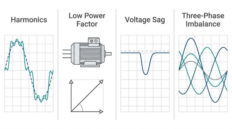
2.1 Harmonic Distortion
Harmonics are voltage or current components at integer multiples of the fundamental power
frequency. In a 60 Hz electrical system, for example, the third harmonic is 180 Hz and the fifth
harmonic is 300 Hz.
Common harmonic-producing equipment includes VFDs, UPS rectifiers, industrial rectifiers,
switching power supplies, and electronic lighting drivers.
Excessive harmonic currents can increase transformer and conductor heating, overload neutral
conductors in certain three-phase, four-wire systems, interfere with sensitive equipment, and
contribute to capacitor bank stress or resonance.
Engineers should evaluate current harmonic distortion (THDi), voltage harmonic distortion
(THDv), the harmonic spectrum, loading conditions, and the applicable measurement requirements.
A high THDi reading alone does not establish the complete condition of the electrical system.
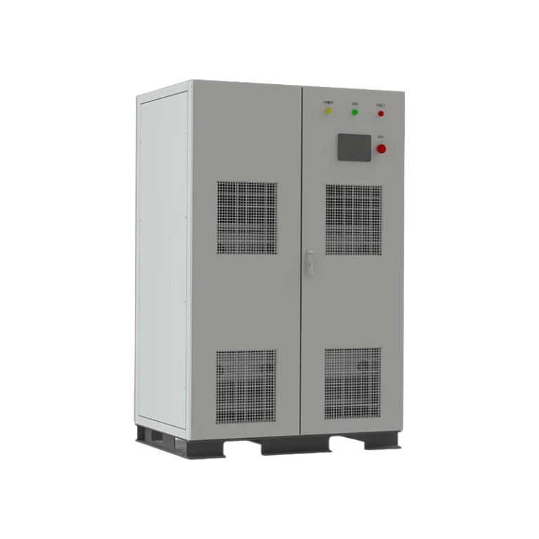
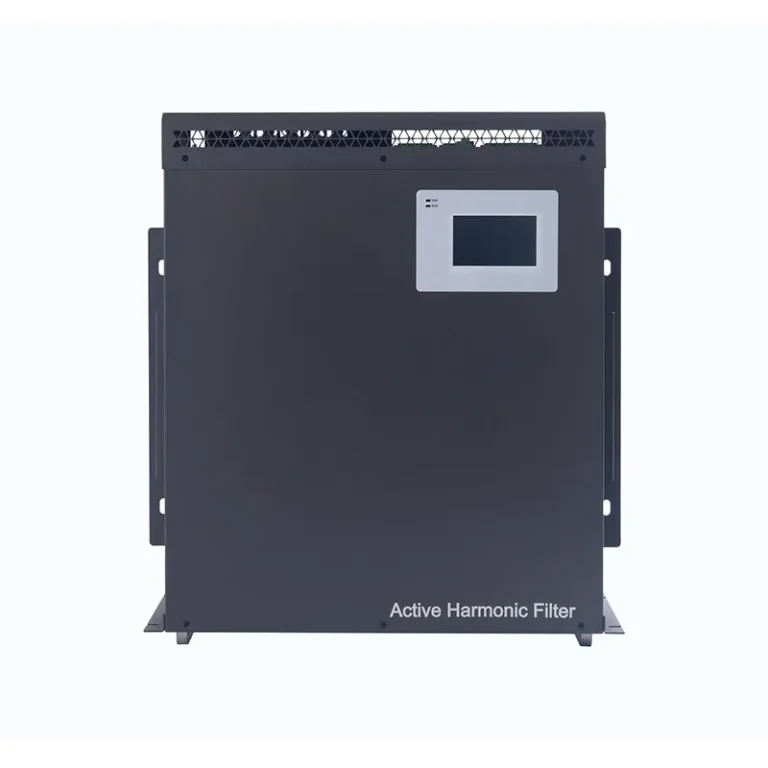
For facilities with significant nonlinear loads, an
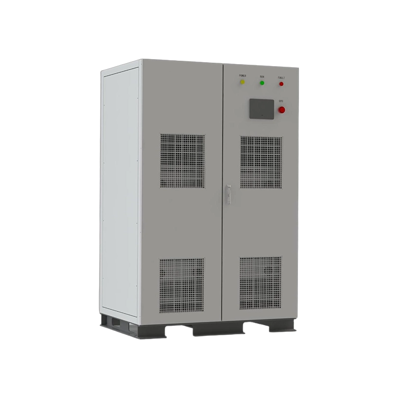
Active Harmonic Filter (AHF)
may be suitable for dynamically compensating harmonic currents.
2.2 Low Power Factor and Excessive Reactive Power
Induction motors, transformers, compressors, and other inductive loads require reactive power
to establish their magnetic fields. When reactive power demand is high, the facility may operate
at a lower power factor than desired.
A low power factor can increase current for a given amount of useful real power, contributing
to additional conductor losses and consuming capacity in transformers, cables, and switchgear.
Depending on the utility tariff and service agreement, it may also result in reactive power charges
or power factor penalties.
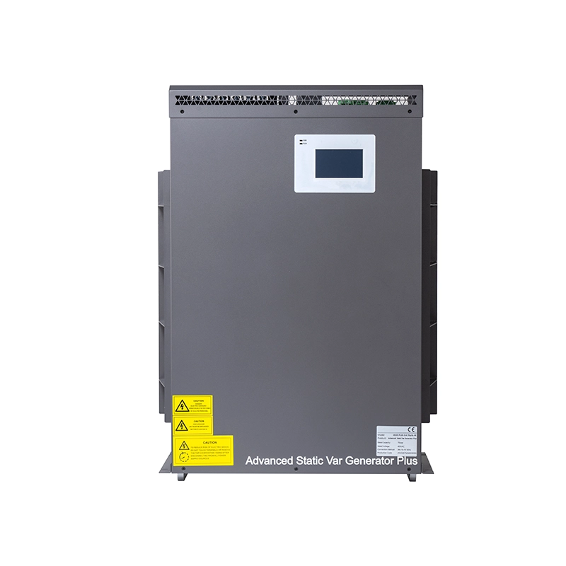
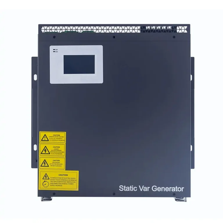
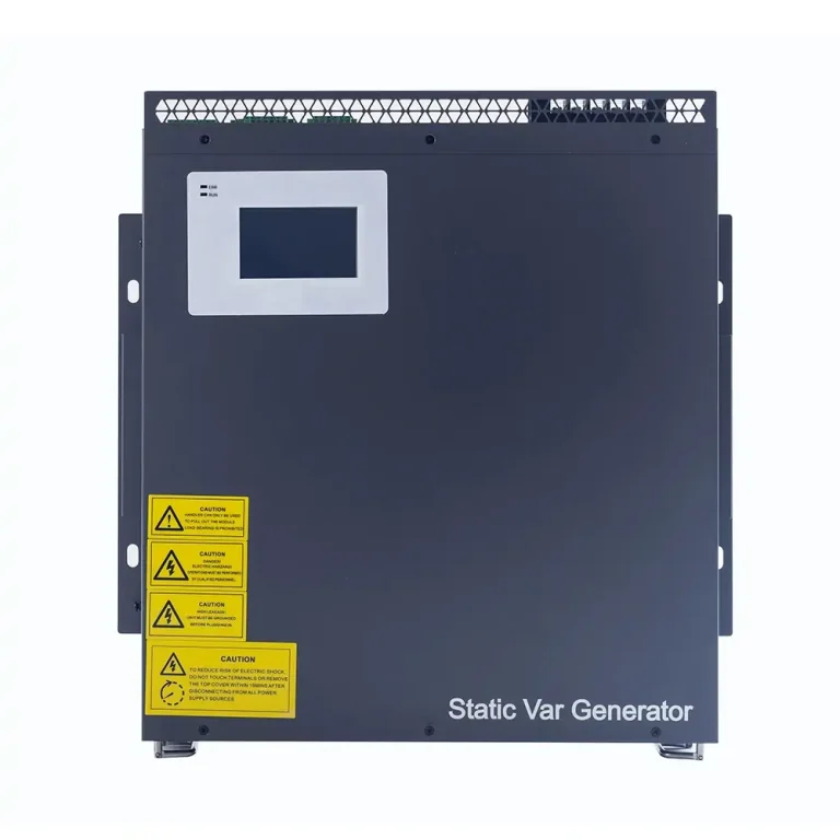
A Static Var Generator (SVG) provides dynamic reactive power compensation by injecting or
absorbing reactive current. Conventional capacitor banks may also be appropriate where loads
are relatively stable and the system has been checked for harmonic resonance.
Before choosing a solution, engineers should review the utility billing structure, load profile,
target power factor, and existing capacitor equipment. Improving power factor does not
automatically eliminate every utility charge.
2.3 Voltage Sags, Swells, and Short Interruptions
A voltage sag is a temporary reduction in RMS voltage. It may result from an upstream electrical
fault, the starting of a large motor, or a sudden change in system loading. A voltage swell is
a temporary increase in RMS voltage, while an interruption involves a more severe loss of supply.
Sensitive PLCs, industrial controllers, robotics, semiconductor equipment, and variable-speed
drives may respond differently to the same disturbance. Even a short voltage sag can interrupt
a process if the affected equipment cannot tolerate the voltage magnitude and duration involved.
Effective mitigation depends on the disturbance and the equipment’s ride-through capability.
Options may include improving upstream system performance, using suitable control power supplies,
installing a properly engineered dynamic voltage restorer (DVR), or providing UPS protection
for critical loads.
These technologies serve different purposes. An SVG is primarily designed for reactive power
compensation, while a DVR addresses voltage disturbances through series voltage injection.
A UPS provides backup power within its designed capacity and operating limits.
2.4 Three-Phase Imbalance and Voltage Flicker
Uneven single-phase loading can create phase-current imbalance in commercial buildings,
offices, data centers, and facilities with mixed single-phase and three-phase equipment.
Significant imbalance can increase motor losses, reduce operating efficiency, and contribute
to neutral conductor loading.
Third-harmonic currents generated by certain single-phase nonlinear loads can add together
in the neutral conductor of a three-phase, four-wire system. Neutral current must therefore
be evaluated rather than assumed to be negligible.
Voltage flicker is associated with rapid voltage fluctuations that may be caused by arc furnaces,
welding equipment, crushers, or other rapidly changing loads. It can affect lighting comfort
and indicate that the electrical system is experiencing demanding operating conditions.
Depending on the measured problem, engineers may consider load redistribution, an AHF with
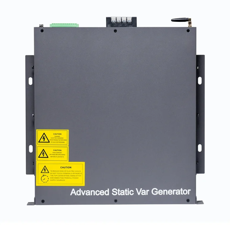
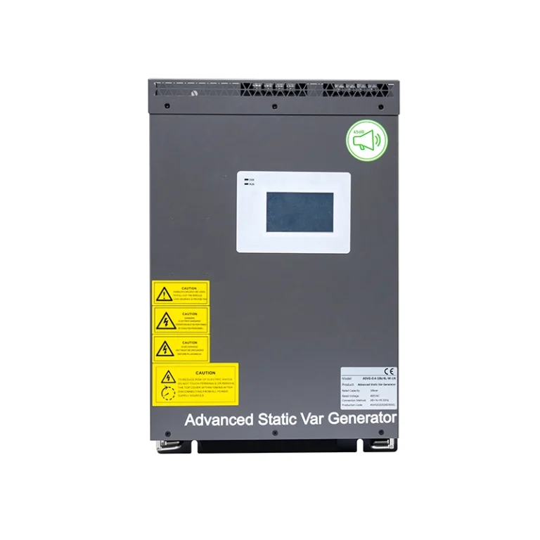
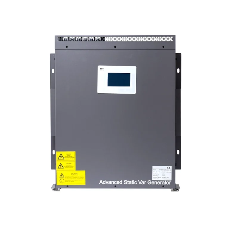
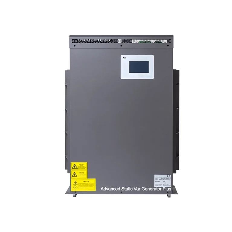
suitable neutral-current compensation, an SVG, or an Advanced Static Var Generator (ASVG).
The final selection should reflect the actual current waveform, system configuration, and
required compensation performance.
3. Industrial Facilities vs. Commercial Buildings: Different Priorities
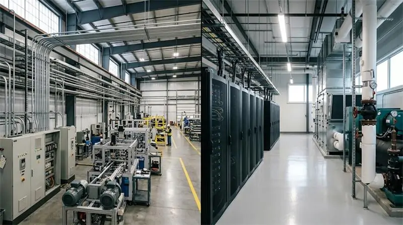
Factories and commercial buildings may use similar electrical technologies, but their operating
priorities and failure consequences are often different.
| Evaluation Factor | Industrial Facilities | Commercial Buildings |
|---|---|---|
| Typical Loads | VFDs, motors, robotics, industrial rectifiers, welding equipment | HVAC systems, elevators, LED lighting, UPS systems, EV chargers |
| Primary Objective | Production continuity and reduced unplanned downtime | Building reliability, electrical safety, and efficient operation |
| Key Concerns | Harmonics, voltage sags, reactive power, rapid load changes | Neutral loading, harmonic distortion, phase imbalance, reactive power |
| Typical Mitigation | AHF, SVG, ASVG, process-specific voltage protection | AHF, SVG, ASVG, load balancing, appropriate UPS protection |
| Performance Indicators | Process availability, THDi, voltage events, power factor | THDv, neutral current, phase balance, energy and demand data |
3.1 Power Quality in Manufacturing Plants
Manufacturing plants often have highly variable loads. Welding stations, large motors, robotic
production lines, and high-power drives can produce rapidly changing electrical demand.
A practical industrial power quality assessment should examine the main distribution bus,
major production feeders, sensitive control circuits, and equipment associated with recurring
interruptions. Measurements should be correlated with machine operating states and production
events whenever possible.
3.2 Power Quality in Commercial and Critical Buildings
Commercial facilities often combine HVAC equipment, elevators, lighting, office electronics,
EV charging, and IT infrastructure. The challenge is to maintain stable operation across
different load types without unnecessarily consuming distribution capacity.
Data centers and other critical facilities require additional attention to UPS performance,
cooling-system loads, neutral currents, phase balance, and the interaction between power
conditioning equipment and the electrical distribution system.
For these environments, power quality mitigation should complement—not replace—proper
grounding, overcurrent protection, equipment coordination, and a professionally designed
electrical distribution system.
4. Power Quality Mitigation Technologies and System Solutions
No single device can correct every power quality problem. The most effective solution matches
the technology to the measured disturbance, load characteristics, electrical system design,
and performance requirements.
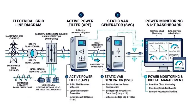
4.1 Active Harmonic Filters (AHF)
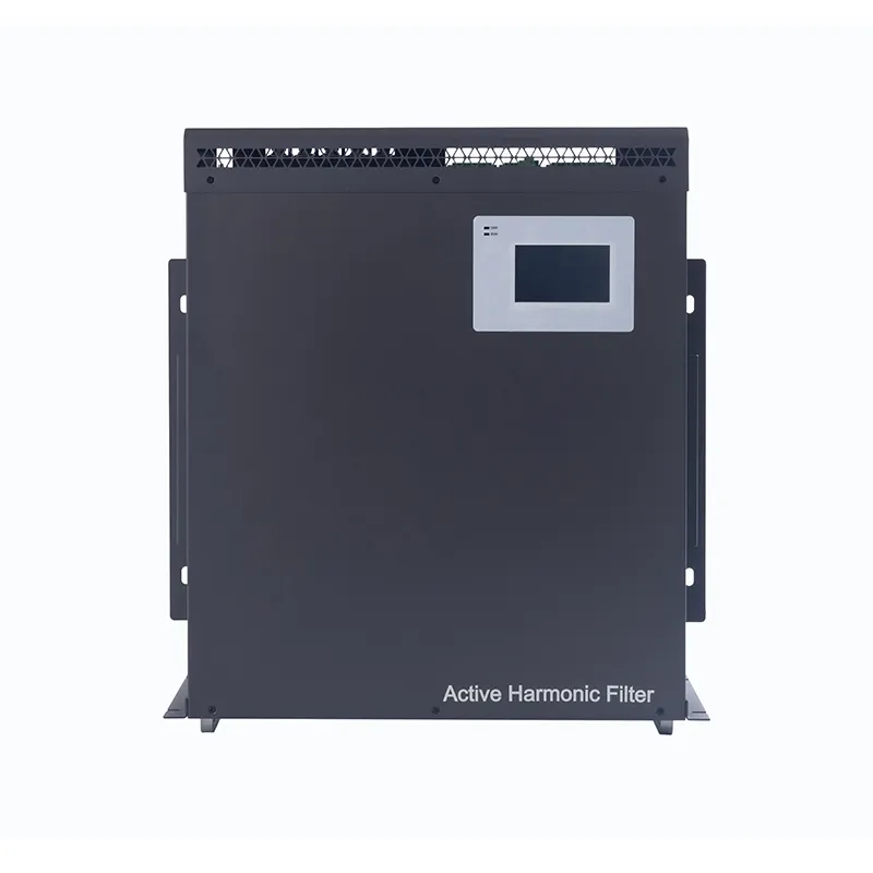
An Active Harmonic Filter measures load current, identifies selected harmonic components,
and injects compensating current to reduce harmonic distortion.
Compared with a fixed passive filter, an AHF can adapt its compensation as load conditions change.
Depending on its design, it may also support phase-current balancing and neutral-current
compensation.
AHF solutions are commonly evaluated for facilities with multiple VFDs, UPS rectifiers,
electronic loads, and other nonlinear equipment. Engineers should confirm the available
compensation current, target harmonic orders, installation point, system impedance, and
expected performance under representative loading conditions.
Explore
GEYA Active Harmonic Filter Solutions
for product options and application details.
4.2 Static Var Generators (SVG)
An SVG dynamically supplies or absorbs reactive current to improve power factor and support
reactive power management. Its continuously adjustable output can be particularly useful
when motor loads, compressors, or production cycles cause frequent changes in reactive demand.
Unlike conventional switched capacitor banks, an SVG does not rely on switching fixed
capacitor stages to achieve each change in compensation output. However, correct sizing,
control settings, current capacity, and system compatibility remain essential.
SVG selection should be based on measured reactive power demand, target power factor,
system voltage, load dynamics, and the presence of harmonic distortion.
4.3 Advanced Static Var Generators (ASVG)
Facilities that experience harmonic distortion, low power factor, and three-phase current
imbalance simultaneously may benefit from an integrated compensation architecture.
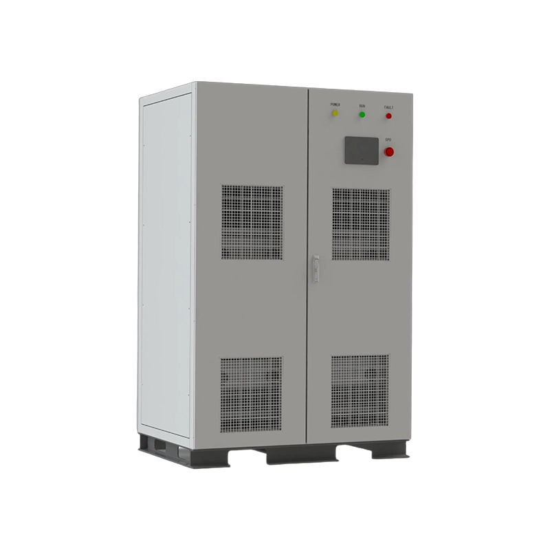
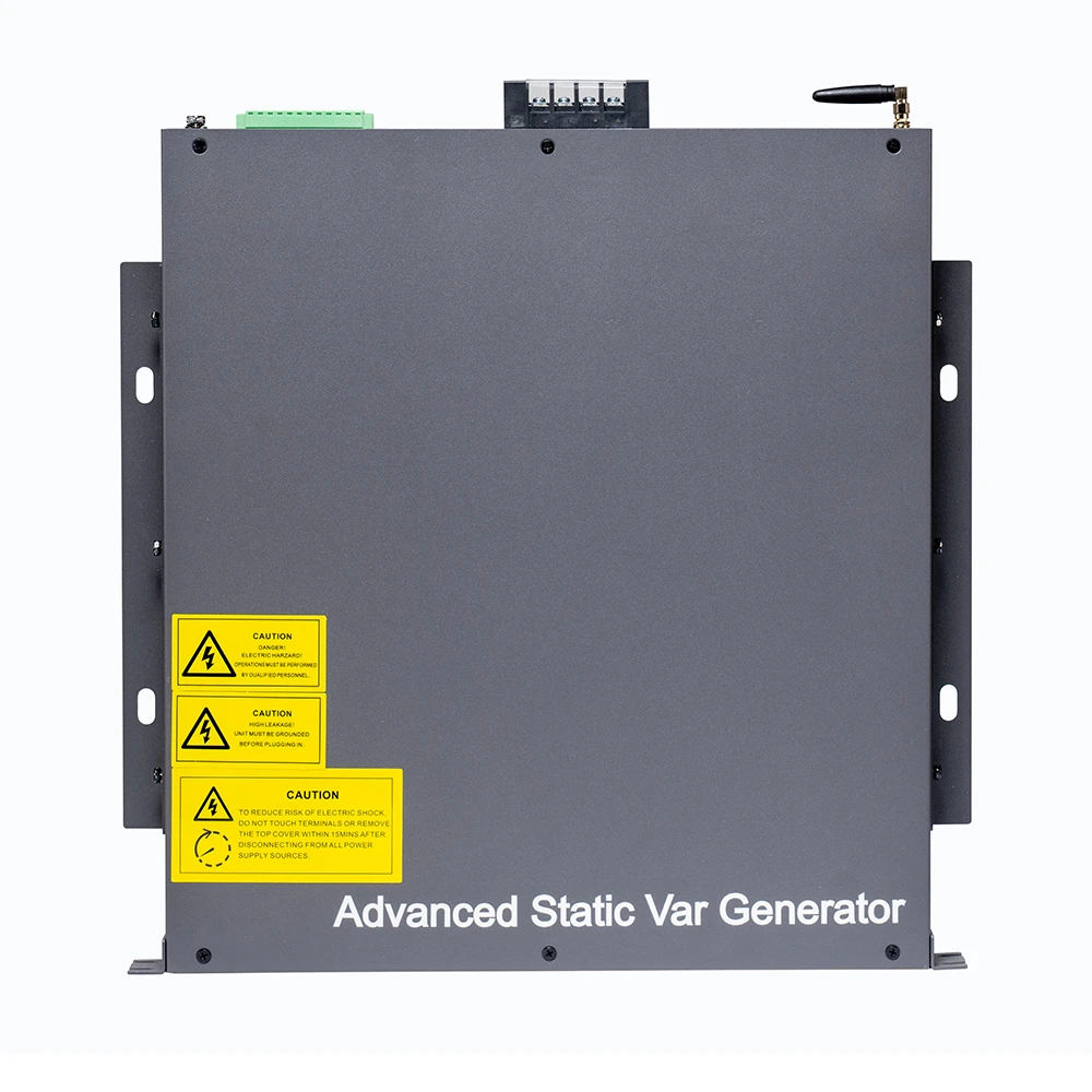
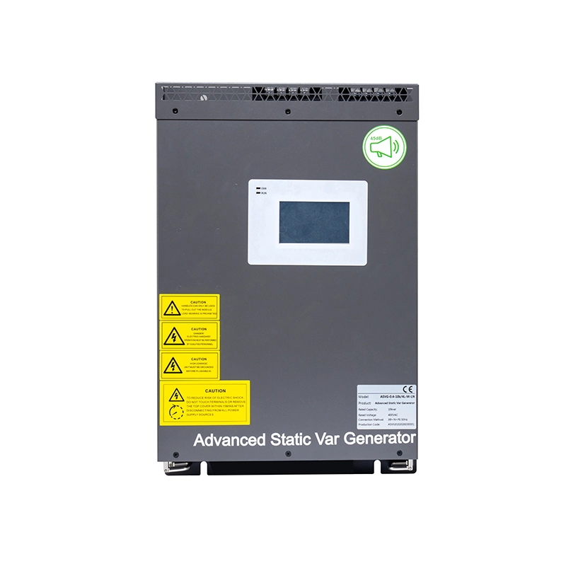
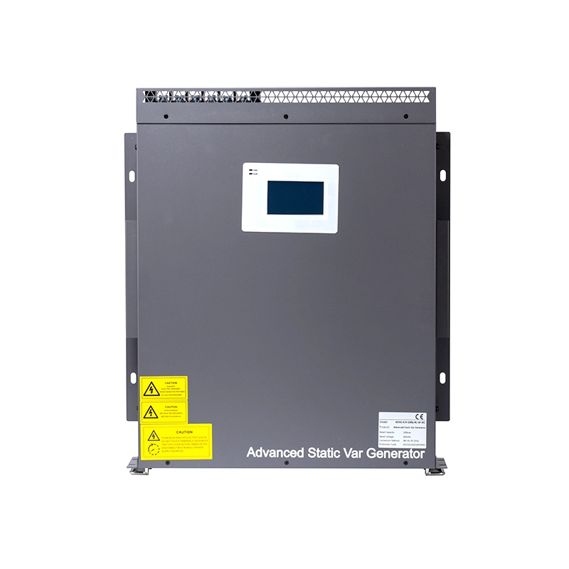
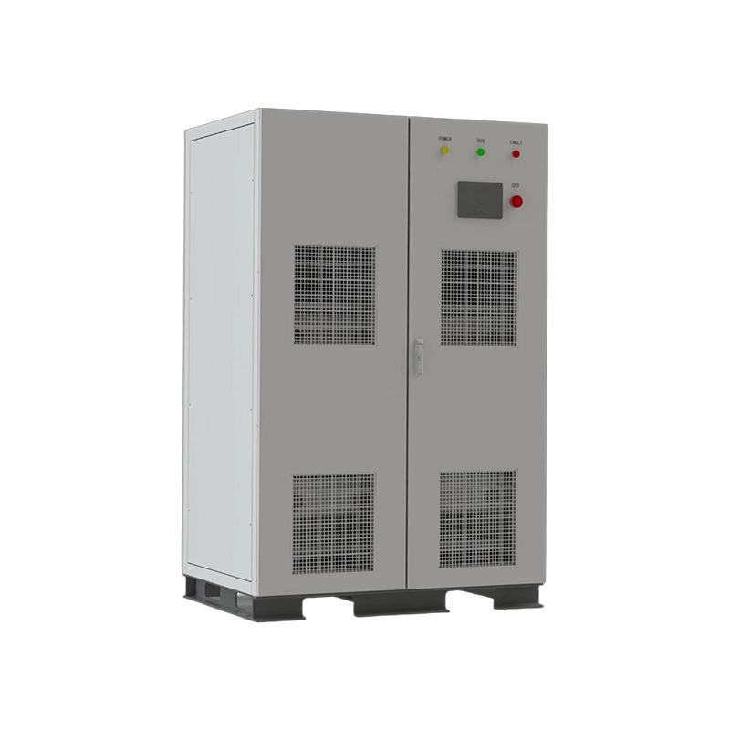
An ASVG can combine reactive power compensation, harmonic mitigation, and phase-current
balancing in one system, subject to the model’s supported functions and available capacity.
An integrated approach may simplify equipment coordination where several problems occur
at the same electrical connection point.
Before choosing an ASVG, compare its individual compensation ratings, operating modes,
neutral-current capability, and performance under combined loading. A multifunctional
device must still be sized for the total compensation duty it is expected to perform.
Learn more about
GEYA Power Quality Management Solutions
and evaluate the appropriate combination of active compensation technologies for your facility.
4.4 Passive Harmonic Filters and Hybrid Systems
Passive harmonic filters use combinations of capacitors, inductors, and, where applicable,
damping components to provide filtering at selected frequencies. They can be economical
for predictable loads with well-characterized harmonic spectra.
However, passive filters must be engineered carefully because their interaction with system
impedance and capacitor banks can create resonance or amplify distortion under certain
operating conditions.
Hybrid systems combine active and passive technologies when the application benefits from
both. The design should consider load variability, harmonic spectrum, installation cost,
maintenance requirements, and the consequences of changing operating conditions.
4.5 Voltage Sag Protection and Critical Power Systems
Voltage sag protection requires a separate assessment from ordinary reactive power
compensation. A facility should identify the sensitive loads, characterize voltage events,
and determine the minimum ride-through capability required by the process.
A dynamic voltage restorer may help compensate voltage disturbances, while an appropriately
selected UPS can support critical control systems, IT equipment, or other protected loads.
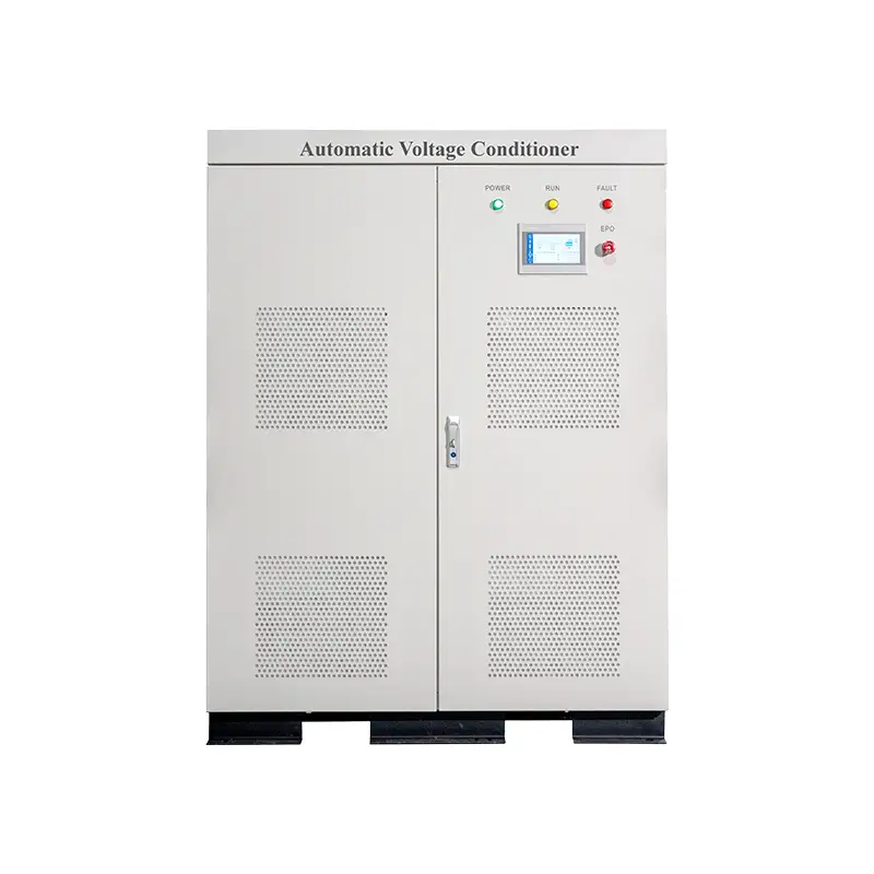
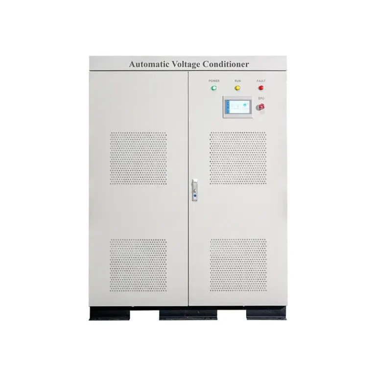
Automatic voltage control equipment may also be appropriate for applications requiring
voltage regulation within its specified operating range.
The design must account for disturbance depth and duration, load power, available fault current,
transfer or injection characteristics, bypass arrangements, and the required backup duration.
Neither a voltage regulator nor an ordinary SVG should be assumed to provide uninterrupted
power during every supply interruption.
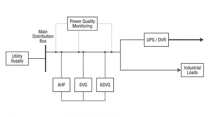
5. Digital Monitoring and Predictive Maintenance
Power quality equipment is most effective when it is supported by reliable measurements.
Monitoring helps engineers distinguish between recurring disturbances, changing load
conditions, equipment-related problems, and upstream supply events.
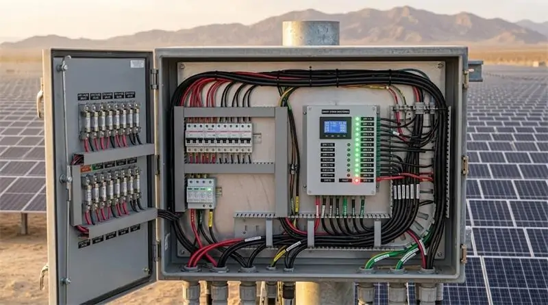
5.1 Establish a Multi-Level Monitoring Architecture
A practical monitoring strategy may include a power quality analyzer at the service entrance,
multifunction meters at major distribution panels, and dedicated monitoring at sensitive
production equipment or critical building systems.
Measurement locations should be selected according to the investigation objective. Monitoring
only the main incoming supply may not reveal the conditions at an individual machine or
downstream feeder.
5.2 Track Meaningful Electrical Indicators
Depending on the application, useful indicators include:
- Voltage and current total harmonic distortion (THDv and THDi).
- Individual harmonic magnitudes and the harmonic spectrum.
- True power factor and reactive power demand.
- Phase voltage and current imbalance.
- Voltage sag, swell, interruption, and transient event records.
- Neutral conductor current and relevant thermal measurements.
- Real power demand, energy consumption, and equipment operating conditions.
Where formal compliance evaluation is required, use appropriate instruments, measurement
intervals, aggregation methods, and reporting procedures. A general-purpose meter is not
automatically equivalent to an instrument designed for a specific power quality measurement
class.
5.3 Apply Data to Maintenance Decisions
Historical trends can help maintenance teams identify recurring electrical events, evaluate
equipment loading, and prioritize investigations. When synchronized with production data,
electrical measurements can also help identify the operating conditions associated with
equipment trips or process interruptions.
Predictive maintenance should be based on validated indicators and engineering interpretation.
Power quality data alone cannot reliably predict every transformer temperature excursion,
motor insulation failure, or equipment lifetime.
For larger facilities, monitoring can be integrated with building management systems (BMS),
supervisory control and data acquisition (SCADA), or industrial Internet of Things (IIoT)
platforms, subject to system compatibility and cybersecurity requirements.

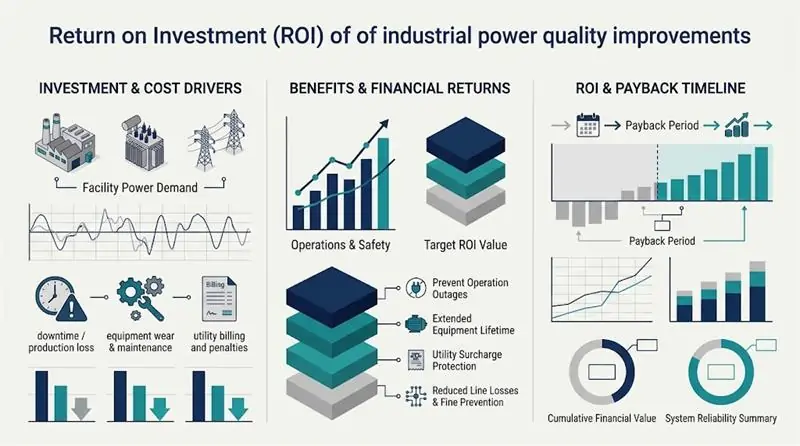
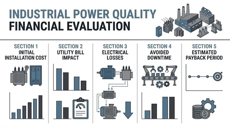
6. Power Quality ROI: Evaluating the Business Case
Power quality improvements should be evaluated using measurable operational and financial
indicators rather than relying on generic energy-saving claims.
6.1 Direct Financial Benefits
Depending on the facility’s electrical conditions and utility tariff, power quality improvements
may reduce certain reactive power charges, lower avoidable electrical losses, and release
usable capacity in transformers, conductors, and distribution equipment.
Better utilization of existing infrastructure may also delay the need for an electrical service
upgrade. However, harmonic mitigation and power factor correction do not automatically
reduce billed peak demand, and neither should be assumed to produce a fixed percentage
reduction in total energy consumption.
Savings should be calculated using actual billing data, measured load profiles, equipment
losses, and the applicable utility rate structure.
6.2 Avoided Downtime and Operational Losses
For manufacturing facilities, the financial impact of an electrical disturbance may extend
beyond the cost of lost electricity. Production interruption can lead to scrap, rework, lost
output, labor inefficiency, restart procedures, and missed delivery commitments.
A useful analysis estimates the frequency of relevant events, the probability that the proposed
solution will prevent or reduce their impact, and the financial consequence of each event.
These assumptions should be supported by maintenance records, production data, and
engineering measurements whenever possible.
6.3 A Practical ROI Calculation
Facilities can use the following framework to estimate the financial case for a proposed
power quality project.
- Annual net benefit:
verified annual savings plus estimated avoided operational losses, minus additional
annual operating and maintenance costs. - Simple payback period:
initial installed project cost divided by annual net benefit, provided annual net benefit
is positive. - ROI:
net financial benefit over the selected evaluation period divided by the relevant investment
cost, using clearly stated assumptions.
For example, a facility that experiences repeated production interruptions may justify a project
primarily through avoided downtime, while a commercial building with stable loads may focus
more heavily on utility charges and electrical capacity utilization.
The business case should separate verified savings from estimates and avoid counting the same
benefit twice. For capital-intensive projects, a discounted cash flow analysis may provide a
more useful comparison than simple payback alone.
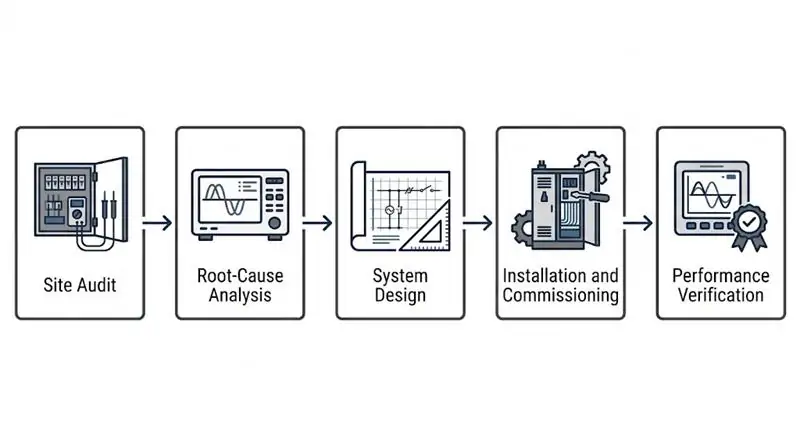
7. A Step-by-Step Implementation Roadmap
A structured implementation process reduces the risk of oversizing equipment, overlooking
the real source of a disturbance, or investing in a solution that does not address the facility’s
primary operational problem.
Step 1: Conduct a Power Quality Audit
Review single-line diagrams, utility bills, equipment inventories, maintenance records, and
reported electrical events. Install suitable monitoring equipment at selected points to establish
a representative baseline.
A monitoring period of 7–14 days can be a useful starting point for some facilities, but the
appropriate duration depends on production cycles, intermittent loads, operating schedules,
and the disturbance being investigated. Rare events may require longer monitoring.
Step 2: Identify Root Causes and Define Performance Targets
Analyze the measurements and correlate events with load conditions. Determine whether the
primary issue is harmonic distortion, reactive power, phase imbalance, voltage instability,
or a combination of problems.
Define the required performance targets and applicable standards before selecting equipment.
In the United States, IEEE 519 may be relevant to harmonic control at the point of common
coupling (PCC), while other standards and contractual requirements may apply depending
on the facility and application.
Step 3: Design and Verify the Proposed Solution
Select the appropriate combination of AHF, SVG, ASVG, voltage protection, and monitoring
equipment based on measured demand and system characteristics.
The engineering review should consider available fault current, transformer capacity, cable
sizing, protective device coordination, harmonic resonance, thermal conditions, and the
required compensation capacity. Modeling or simulation may be appropriate for complex systems.
Step 4: Install and Commission the Equipment
Develop an installation and commissioning plan that addresses electrical safety, outage
coordination, equipment integration, control settings, and communication requirements.
Modular construction may simplify capacity expansion, but hot-swapping or live maintenance
must never be assumed unless the equipment is specifically designed and approved for that
procedure.
Step 5: Verify Results and Establish Ongoing Monitoring
Repeat measurements under comparable operating conditions after commissioning. Compare
harmonic levels, power factor, phase balance, voltage events, and other agreed indicators
with the baseline.
Document the results, confirm that the equipment is operating within its rated limits, and
establish alarm thresholds and periodic review procedures. If the expected improvement is
not achieved, investigate the remaining sources and adjust the design or operating settings
as necessary.
8. Choosing the Right Power Quality Partner
Selecting a power quality solution involves more than comparing product prices or nominal
compensation ratings. The supplier should be able to connect the measured electrical problem
with a technically appropriate equipment configuration.
Before proceeding, facility owners and engineering teams should evaluate:
- Technical fit:
whether the proposed technology addresses the measured disturbance and operating conditions. - Engineering support:
whether the supplier can review single-line diagrams, load data, and project requirements. - System integration:
whether the equipment supports the required electrical configuration, communication interfaces,
and installation constraints. - Performance verification:
whether acceptance criteria and post-installation measurements are clearly defined. - Lifecycle considerations:
whether commissioning, maintenance, technical documentation, and future expansion are addressed.
GEYA provides power quality equipment and solutions covering active harmonic filtering,
dynamic reactive power compensation, combined compensation, and voltage control.
The appropriate configuration should be determined from the facility’s electrical measurements
and project requirements.
Explore
GEYA Power Quality Management Solutions
to learn more about available technologies and potential applications.
9. Frequently Asked Questions About Industrial Power Quality
What is industrial power quality management?
Industrial power quality management is the process of measuring, analyzing, and mitigating
electrical disturbances such as harmonic distortion, low power factor, voltage sags, and
three-phase imbalance. The objective is to improve electrical system performance and support
reliable facility operation.
What is the best solution for harmonic distortion in a factory?
An Active Harmonic Filter (AHF) is often considered when nonlinear loads create changing
harmonic currents. The appropriate solution depends on the harmonic spectrum, load profile,
system impedance, required compensation capacity, and applicable limits.
What is the difference between an AHF and an SVG?
An AHF primarily compensates harmonic currents, while an SVG primarily provides dynamic
reactive power compensation and power factor correction. Facilities with both problems may
need coordinated equipment or an integrated solution such as an ASVG, depending on the
available functions and required capacity.
Can power factor correction reduce electricity bills?
It can reduce certain reactive power charges or power factor penalties when these are included
in the applicable utility tariff. It may also reduce current-related losses and improve capacity
utilization. Actual savings depend on the billing structure, load profile, and existing system.
Can an SVG protect equipment from voltage sags and power outages?
An SVG primarily compensates reactive power and is not a substitute for a UPS or a dedicated
voltage sag mitigation system. Facilities requiring ride-through or backup power should
evaluate appropriate voltage protection, UPS capacity, and the duration of the disturbance.
How long should a power quality audit last?
A 7–14 day measurement period can provide a useful baseline for some facilities, but the
monitoring period should reflect the operating schedule and the frequency of the events being
investigated. Longer monitoring may be necessary for intermittent processes or rare disturbances.
Which power quality standards are relevant to U.S. facilities?
IEEE 519 is commonly referenced for harmonic control in electric power systems, particularly
at the point of common coupling. Other IEEE, IEC, utility, and contractual requirements may
apply depending on the type of disturbance, equipment, and project. Engineers should verify
the current applicable edition and the specific compliance requirements for each installation.
How can a facility estimate the ROI of a power quality project?
Estimate the verified financial impact of utility charges, electrical losses, released distribution
capacity, and avoided operational interruptions. Subtract additional operating costs and compare
the annual net benefit with the installed project cost. Use site-specific measurements rather
than assuming a universal energy-saving percentage.
10. Conclusion: Build a Measurement-Led Power Quality Strategy
Reliable electrical performance is essential to modern manufacturing and commercial building
operations. Harmonic distortion, excessive reactive power, voltage disturbances, and phase
imbalance can affect equipment performance, usable distribution capacity, maintenance
requirements, and operational continuity.
A sustainable power quality strategy begins with measurement, identifies the root causes of
electrical disturbances, and applies the right combination of active filtering, reactive power
compensation, voltage protection, and monitoring.
For facilities planning a power quality improvement project, the next step is to review the
electrical system data, define measurable performance targets, and evaluate suitable mitigation
options before committing to equipment.
Need help evaluating your facility’s power quality requirements?
Review
GEYA Power Quality Management Solutions
and contact the GEYA team to discuss your application, load profile, and project requirements.